
2026年11月10日
Compare manual vs automated shell manufacturing line costs speed quality labor needs and output to choose the right production solution
Manual vs Automated Shell Manufacturing Line Core Architecture
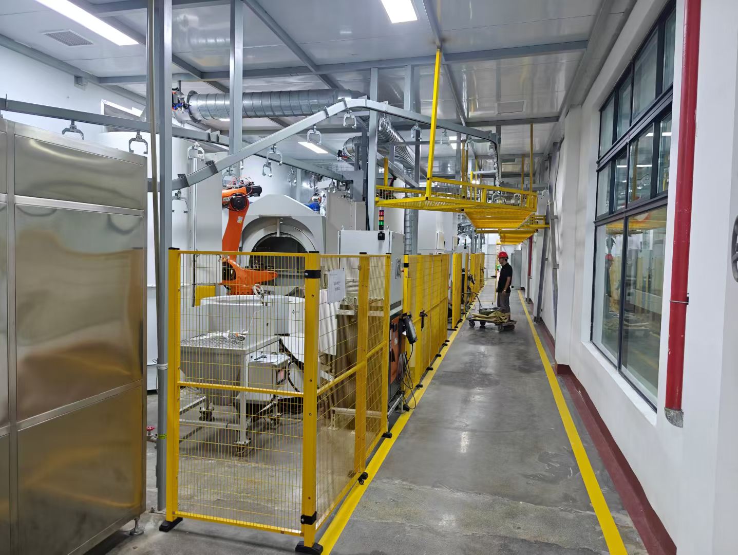
When evaluating the transition from manual to automated processes, we focus on the fundamental architecture of the shell room. Our engineering perspective centers on how these systems handle the delicate transition from wax tree to ceramic mold.
Workstation Layout and Handling
- Manual Lines: Rely on individual workstations equipped with independent slurry dipping tanks and localized rainfall sanders or fluidized bed units. Handling is typically facilitated by manual hoists or pneumatic lifters, requiring high operator skill to maintain consistent immersion angles.
- Automated Lines: Utilize integrated multi-axis industrial articulated robots. These systems standardize the movement path for every cluster, eliminating the variability inherent in manual handling.
Environmental and Control Systems
- Drying Control: Manual workflows often utilize offline ambient racking, which is highly susceptible to humidity and temperature fluctuations. In contrast, automated lines incorporate continuous drying tunnels. These tunnels provide precise, repeatable climate control, ensuring the green strength of the shell develops uniformly.
- System Management: We move away from manual monitoring toward centralized PLC and HMI (Human-Machine Interface) recipe management. This transition allows for the digital tracking of every dipping cycle, ensuring every mold meets strict metallurgical specifications.
By integrating robotic handling with automated climate controls, the manual vs automated shell manufacturing line comparison highlights a shift from operator-dependent craftsmanship to predictable, high-precision industrial production.
Comparative Technical Specifications for Shell Manufacturing Lines
When evaluating a Manual vs Automated Shell Manufacturing Line, our engineering team focuses on measurable throughput and precision metrics. The transition from manual labor to automated robotic systems shifts production from variable human performance to consistent, high-repeatability cycles.
Performance and Capacity Matrix
| Feature | Manual Shelling Line | Automated Robotic Line |
|---|---|---|
| Payload Capacity | Limited by operator strength | High (supports heavy/complex trees) |
| Daily Throughput | Low to moderate | High (consistent 24/7 potential) |
| Cycle Repeatability | Variable (human factor) | High (precision pathing) |
| Shell Thickness | Subject to manual dipping speed | Uniform (controlled robotic dip) |
| Operator Need | High (multiple per line) | Low (supervision only) |
Engineering and Operational Impacts
- Precision and Uniformity: Robotic cells ensure that every cluster follows the exact same dipping angle and drainage time, which is critical when producing parts from 4140 alloy steel properties, uses, and specs guide. Automated systems significantly reduce variations in shell wall thickness compared to manual dipping.
- Throughput Metrics: Manual lines are constrained by the physical stamina of the operator and the inconsistent timing of slurry drainage. Automated systems provide predictable daily mold counts, allowing for tighter production scheduling.
- Infrastructure Requirements: While automated lines require a larger initial footprint for robotic arms and drying tunnels, they maximize utility efficiency by reducing the floor space needed for manual staging. Power requirements are higher for robotic systems, but this is offset by significant reductions in labor overhead and scrap rates.
- Labor Efficiency: A manual line often requires a full team to handle individual dipping, sanding, and transport. An automated setup allows us to reallocate that headcount to higher-value roles, such as quality inspection or shell room management, ensuring the entire investment casting shell building line operates at peak efficiency.
Operational Performance and Engineering Metrics
Evaluating a manual vs automated shell manufacturing line comes down to measurable physical output on the foundry floor. In our casting operations, we evaluate shell room performance by coating repeatability, refractory packing density, and scrap reduction.
Slurry Coating Precision, Dynamic Angles, and Rotational Drainage
Uniform slurry film thickness requires controlled acceleration and exact manipulation as the pattern enters and exits the bath:
- Manual Workstations: Operators manipulate patterns based on visual judgment and physical feel. Angles vary with operator fatigue, leading to uneven drainage, slurry pooling at wax fillets, and irregular prime coats.
- Automated Dipping Cells: A multi-axis robotic dipping system executes programmed angular vectors down to fractions of a degree. Continuous 360-degree compound rotation during withdrawal balances wet film weight, completely standardizing ceramic shell wall thickness uniformity across high-runner part families.
Stucco Deposition Efficiency and Grain Packing Density
Proper refractory application gives the green shell its mechanical strength before dewaxing:
- Rainfall sander equipment and fluidized bed stuccoing machines integrated into automated systems ensure consistent fall velocity and kinetic impact of the refractory grains. This creates dense, interlocking grain packing across primary and backup coats.
- Manual stuccoing struggles with blind spots in complex core clusters, leading to loose, uneven grain coverage and soft zones vulnerable to cracking during autoclaving.
Elimination of Air Entrapment, Dry Spots, and Edge Thinning
Complex wax clusters create turbulence that traps air pockets in recessed features:
- Dynamic motion control: Programmed dipping profiles gently submerge patterns at calibrated entry speeds to let displaced air escape naturally.
- Zero edge thinning: Multi-axis articulated robots hold parts at precise draining angles to stop liquid pull-back along sharp radii.
- Complete slurry contact: Automated immersion eliminates dry spots caused by rush or operator hesitation, preserving core integrity similar to the structural baselines detailed in our sand mold casting guide.
Shell Structural Integrity, Scrap Reduction, and Mold Run-Out Prevention
Defects in the shell room trigger immediate scrap at the casting deck:
| Metric | Manual Shelling Line | Automated Robotic Cell |
|---|---|---|
| Shell Layer Repeatability | High operator variance (±15–25%) | Tightly controlled (±2–3%) |
| Green Shell Strength | Inconsistent bond strength | Uniform structural integrity across all coats |
| Mold Run-Out Rates | Elevated risk from localized thin spots | Near-zero run-outs from consistent wall build |
| Dewaxing Scrap | 4% to 8% typical shell failure | Consistently below 0.5% |
By replacing physical variability with recipe-driven repeatability, automated shelling lines stop structural shell failures before the mold ever reaches the pour floor.
Total Cost of Ownership and ROI Analysis
Evaluating a Manual vs Automated Shell Manufacturing Line requires balancing upfront capital commitments against direct operational returns. While a manual line appears cheaper on day one, an automated ceramic mold making system transforms variable production liabilities into fixed, predictable outputs over the life of the foundry.
Initial CapEx Breakdown and Commissioning Costs
Setting up a dipping room involves fundamentally different capital allocations depending on the chosen configuration:
- Manual Shell Making Workstation: Low baseline CapEx. Outlays center on manual hoists, basic slurry mixing and conditioning tanks, open rainfall sanders, and standard curing racks. Site preparation is minimal, requiring basic three-phase power and local exhaust ducting.
- Robotic Shell Dipping Cell: Higher initial investment covering the heavy-payload articulated robot, precision climate-controlled drying tunnels, automated continuous conveyors, PLC safety interlocks, and dedicated foundations. Engineering commissioning covers multi-axis path teaching, slurry viscosity integration, and dynamic flow testing.
OpEx, Labor Reduction, and Workforce Reallocation
Manual shelling creates chronic exposure to repetitive strain, abrasive dust, and heavy lifting. Shifting to an automated slurry dipping system alters the shop-floor labor balance:
- Headcount Reduction: A traditional manual line requires four to six dedicated operators per shift to manage dipping, stuccoing, and transfer racks. An automated cell reduces this requirement to a single operator managing loading, unloading, and bath maintenance.
- Skill Reallocation: Workers move from physically demanding dipping jobs into higher-value roles like visual inspection, wax assembly, and furnace operations.
- Shift Continuity: Robots do not experience fatigue, maintaining exact cycle timing across three continuous shifts without dipping speed variations or missed dry coats.
Consumable Savings: Slurry Evaporation and Sand Recovery
Material yield significantly impacts overall cost per mold, particularly when producing tight-tolerance parts found in our aluminum alloy casting guide for die, sand, and investment processes.
| Cost Driver | Manual Shell Line Impact | Automated Robotic Cell Impact |
|---|---|---|
| Slurry Evaporation | Open tanks lead to constant solvent loss and unstable binder balance. | Automated covers and climate-matched enclosures drop evaporation rates by up to 25%. |
| Stucco Wastage | Manual dusting creates floor spillage and high sand discard rates. | Enclosed rainfall sanders and fluidized beds recycle refractory grain at 92%+ recovery efficiency. |
| Slurry Drag-out | Irregular manual withdrawal causes excessive slurry runoff and waste. | Programmed axis manipulation ensures controlled drainage, cutting binder drag-out by 15-20%. |
| Scrap from Run-outs | Operator fatigue causes inconsistent coat thickness, driving shell cracking. | Uniform shell wall thickness practically eliminates mold failure during metal pour. |
Payback Benchmarks for Medium-to-High Volume Foundries
For facilities pouring medium to high volumes, the return on investment for an automated cell follows a distinct financial path:
- High-Mix, Medium-Volume Operations: Typically break even within 18 to 24 months, driven by rapid reductions in scrap, reduced rework, and cutbacks in overtime hours.
- High-Volume Production Facilities: Reach full payback within 12 to 16 months through raw consumable savings, floor space consolidation via overhead drying conveyors, and near-zero mold burst scrap.
- Direct Casting Scrap Reduction: Dropping shell-related scrap from a manual baseline of 4–6% down to below 0.8% delivers instant margin recovery on high-value metal pours.
Modular Scalability and Hybrid Shell Line Configurations
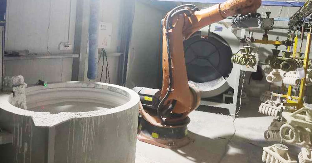
Choosing between a manual vs automated shell manufacturing line is rarely an all-or-nothing decision. We frequently design hybrid architectures that allow foundries to balance capital outlays with targeted process improvements. By combining proven manual tasks with automated transfer and environmental control, you can eliminate production bottlenecks immediately while keeping the door open for full automation later.
Semi-Automated Lines: Manual Dipping with Automated Drying Conveyors
For foundries managing complex, fragile wax assemblies, manual dipping combined with an automated conveyor system offers an ideal middle ground.
- Manual slurry and stucco handling: Operators retain complete tactile control over dynamic angles and slurry drainage for non-standard clusters.
- Continuous drying management: Coated trees transfer directly onto an overhead power-and-free conveyor or multi-tier drying line, eliminating manual cart handling.
- Controlled drying cycles: Programmable index times and climate tunnels ensure each coat reaches target green strength before the next application.
- Footprint optimization: Vertical buffer conveyors utilize overhead ceiling space instead of cluttering floor areas with stationary drying racks.
Foundries adopting this approach often transition smoothly to an automated ceramic shell coating, dipping, stuccoing, and drying system without overhauling their primary facility infrastructure.
Retrofit-Ready Layouts for Future Robotic Cell Expansion
Upgrading from a manual setup should not require tearing down existing shell room assets. We configure retrofit-ready equipment lines that integrate existing slurry conditioning tanks, rainfall sanders, and fluidized beds into future automation envelopes:
- Standardized tank footprints: Peripheral machinery is engineered with unified mounting baselines, making it easy to drop in a multi-axis industrial robot down the road.
- Unified safety zones: Interlocked safety fences, light curtains, and integrated dust extraction hoods are positioned during phase one to accommodate future robot sweeps.
- Central control readiness: Integrated PLC architecture comes pre-wired with open fieldbus nodes, ensuring rapid handshakes with added robotic arms and vision tracking units.
Implementing phased equipment through dedicated robotic material handling for foundries allows you to scale production capacity incrementally alongside real customer demand.
Quick-Change Tooling and Grippers for Varied Wax Tree Geometries
High-mix foundries face the constant challenge of handling disparate wax tree designs without slowing down line throughput. We eliminate setup delays by utilizing quick-change tooling built specifically for diverse cluster profiles:
- Universal pneumatic mechanical chucks: Provide instant, self-centering clamping on hex, round, or tapered runner bars.
- Payload-specific compliance: High-rigidity gripping heads handle wet tree payloads from 25 kg to over 150 kg without introducing deflection or vibration.
- Tool-less changeover: Operators switch mechanical grippers in under two minutes using quick-disconnect air couplings and mechanical locating pins.
- Barcode and RFID tracking: Every wax tree fixture carries an ID tag, prompting the control system to recall the exact dipping sequence, rotation speeds, and drying profiles automatically.
Foundry Sizing Guide: Choosing a Manual vs Automated Shell Manufacturing Line
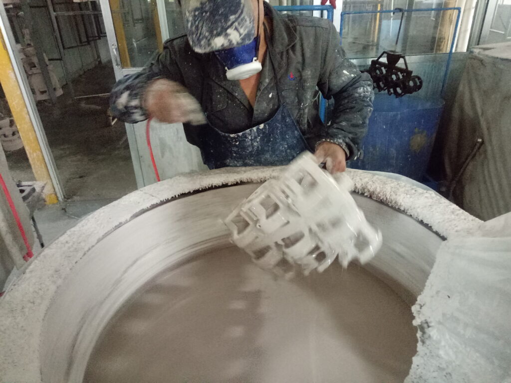
Deciding between a manual layout and a fully automated cell comes down to production volume, tree geometry, and physical plant limitations. We evaluate three primary operational factors before recommending a line configuration.
When Manual Dipping Makes Operational Sense
A manual shell room remains practical for specialized production profiles:
- Low-Volume, High-Mix Batches: R&D prototypes, art castings, and specialty job shops running dozens of differing tree geometries each week.
- Oversized and Heavy Wax Trees: Massive single-part trees or irregular assemblies that exceed standard robot payload envelopes or require custom dipping angles.
- Low Initial CapEx Capacity: Foundries prioritizing low entry costs over high-volume shift throughput.
When to Deploy an Automated Robotic Cell
Robotic automation delivers immediate value under demanding production and quality benchmarks:
- High-Volume, Repeatable Runs: Standardized clusters running multi-shift cycles where manual handling introduces operator fatigue.
- Stringent Quality Specifications: Programs like titanium investment casting for aerospace and medical parts that require uniform ceramic shell thickness, controlled slurry drainage, and traceable batch consistency.
- High Labor Overhead: Plants operating in regions where skilled shell room labor is scarce or expensive.
Plant Infrastructure Constraints
Before finalizing a manual vs automated shell manufacturing line, our team audits three core facility requirements:
| Facility Parameter | Manual Shell Workstation | Automated Robotic Dipping Cell |
|---|---|---|
| Clear Ceiling Height | Standard (2.5 m to 3.0 m / 8–10 ft) | High clearance (minimum 4.0 m to 5.0 m / 13–16 ft) for robot articulation |
| Floor Load Capacity | Standard industrial slab | Reinforced concrete pad engineered for dynamic robot vibration and static payload |
| Dust Collection & HVAC | Localized capture hoods at sanders | Integrated high-volume airflow handling continuous stuccoing and climate-controlled drying tunnels |
Quality Compliance and Equipment Engineering Standards
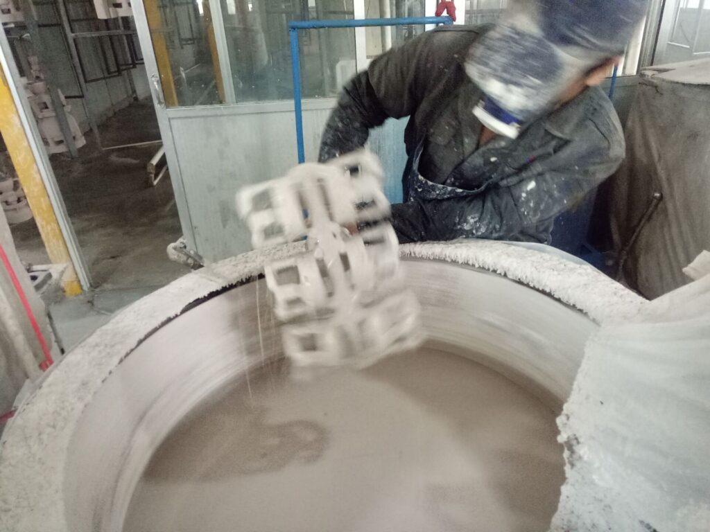
Evaluating a manual vs automated shell manufacturing line requires looking closely at safety compliance, structural build quality, and long-term equipment reliability. Whether you run a high-throughput robotic cell or a series of manual workstations, our engineering team builds every system around strict global standards to protect your operators and maintain continuous production.
CE, ISO 9001, and Foundry Safety Compliance
Every shell room operates in a tough environment filled with airborne ceramic dust, wet slurry, and continuous mechanical movement. We design and certify our hardware to mitigate these operational hazards:
- Automated lines: Fully compliant with CE machinery directives, ISO 9001 manufacturing frameworks, and ISO 10218 industrial robot safety standards. Cells include interlocked safety fencing, zone-based light curtains, integrated dust extraction ports, and hardware-level emergency stop circuits.
- Manual workstations: Engineered to eliminate ergonomic strain on dipping operators. Systems feature counterbalanced pneumatic hoists, anti-slip grated walkways, local exhaust ventilation (LEV) hoods, and IP65-rated electrical components that resist moisture and slurry washdowns.
Factory Acceptance Testing (FAT) and Commissioning
To ensure zero downtime upon arrival at your foundry, we subject every setup to comprehensive Factory Acceptance Testing (FAT) at our production facility before dispatch:
- Dry run verification: 48-hour continuous cycle testing to evaluate drive stability, axis repeatability, and slurry tank agitation.
- Full-load payload profiling: Running articulated robots or manual hoists under maximum rated wax assembly weights to ensure zero structural deflection.
- Process integration checks: Verifying slurry drainage and sand deposition cycles to guarantee that ceramic molds achieve the green strength needed before heading into downstream dewaxing autoclave operations.
- On-site site commissioning: Our field engineers manage line leveling, electrical drops, dry air hookups, and precise robot path calibration directly on your foundry floor.
Remote Telemetry, PLC Monitoring, and Maintenance
Equipment reliability directly affects shell yield. In an automated shell manufacturing line, our central PLC platforms collect and monitor critical operating metrics in real time:
- Predictive maintenance telemetry: Industrial IoT edge gateways monitor axis servo torque, rainfall sander motor currents, and slurry tank mixing speeds to flag mechanical wear before a line stops.
- Real-time recipe monitoring: HMI screens track dip angles, rotational drain speeds, and drying tunnel ambient levels, storing full batch logs for complete aerospace and medical casting traceability.
- Secure remote diagnostics: Our technical support team connects directly via encrypted VPN tunnels to run PLC diagnostics, update software, and troubleshoot line faults without waiting for on-site service calls.
Frequently Asked Questions About Manual vs Automated Shell Manufacturing Lines
How long does it take to transition a foundry from a manual to an automated shell line?
A full switch typically takes between 4 to 8 weeks on-site. We pre-assemble, wire, and test equipment before shipping, which keeps disruption inside your shell room to a minimum.
- Site preparation: 1 to 2 weeks (floor anchoring, utility drops, ventilation routing).
- Mechanical & electrical installation: 1 to 2 weeks.
- Dry cycle and wet commissioning: 1 to 2 weeks.
- Production ramp-up and operator training: 1 to 2 weeks.
Foundries upgrading to our automatic shell coating line for investment casting often run their manual stations alongside the new cell during initial slurry testing to prevent downtime on active client orders.
Is recipe programming complex for operators without robotics experience?
Not at all. Operators do not write code. Our industrial articulated robots run off pre-mapped PLC recipes managed through a standard touchscreen HMI.
- One-touch recipe loading: Dipping depths, multi-axis tilt angles, rotation speeds, and draining times are saved per part number.
- Teaching pendant simplicity: Adjusting paths for a new tree design uses simple jog-and-teach points.
- Safety interlocks: Built-in travel limits prevent the robot arm from colliding with slurry tanks, rainfall sanders, or dry conveyor hooks.
Once a recipe is locked in, any technician can run production batches with zero robotics background.
What is the maximum tree payload capacity for automated robotic dipping cells?
Standard industrial dipping cells handle tree payloads from 50 kg up to 500 kg (110 lbs to 1,100 lbs), including the tree fixture and wet ceramic layers:
- Light-duty cells (50–100 kg): Ideal for small hardware, medical implants, and compact aerospace blades.
- Medium-duty cells (100–250 kg): The industry benchmark for commercial valve bodies, pump impellers, and general automotive castings.
- Heavy-duty systems (300–500 kg+): Built for large structural components, heavy turbine housings, and large industrial clusters.
Manual dipping lines rely on hoist cables and physical balancing, quickly fatiguing operators and causing slurry washing defects on trees exceeding 25 kg.
Can existing slurry tanks and rainfall sanders be retrofitted into a robotic layout?
Yes. If your current mechanical equipment is structurally sound and holds slurry viscosity evenly, we can incorporate it directly into our automated shell coating solutions.
Retrofitting existing machinery usually requires: Adding remote I/O modules to link the tank drives and sanders to the central line PLC. Repositioning units radially to fit within the working envelope of the articulated robot. Adding pneumatic covers, splash shields, and position sensors for automatic opening and closing during dip cycles.
If an older tank cannot maintain continuous temperature or uniform agitation, replacing it with an integrated, variable-speed unit is usually more cost-effective than running continuous field repairs.

 English
 Russian
 German