
2026年9月26日
Discover efficient casting method techniques materials and applications for producing strong precise high quality components and finished products
Core Steps of Any Casting Method
Every successful metal casting operation follows a strict, sequential workflow. While tooling and mold materials vary across different techniques, the core physics of shaping liquid metal into a solid component remains consistent. I manage every casting run through four fundamental stages to guarantee structural integrity, tight tolerances, and minimal defect rates.
Pattern and Mold Preparation
The process begins with accurate tooling. We create a pattern—a physical replica of the exterior geometry of the final part—scaled up slightly to account for thermal contraction as the metal cools.
- Tooling selection: Patterns are machined from wood, resin, or metal depending on production volume and required precision.
- Core placement: If the part features internal passages or complex cavities, we place sand or ceramic cores inside the mold cavity.
- Gating system setup: We design an optimized network of sprues, runners, and risers to guide liquid metal into the cavity smoothly, minimizing turbulence and air entrapment.
Melting and Molten Metal Pouring
Once the mold is clamped and preheated, the base alloy is brought to its specific liquidus temperature in an induction or gas-fired furnace.
- Slag removal and degassing: Before pouring, we skim off surface impurities (dross/slag) and introduce inert gases or fluxing agents to remove dissolved hydrogen that causes gas porosity.
- Pouring control: The molten metal is poured into the mold cavity at tightly controlled temperatures and transfer rates to ensure complete cavity fill without eroding the mold walls.
| Process Variable | Target Objective | Impact on Quality |
|---|---|---|
| Pouring Temperature | Maintained within a ±10°C window | Prevents premature freezing or excessive mold thermal stress |
| Pouring Speed | Continuous, laminar flow | Eliminates cold shuts and prevents air entrapment |
| Degassing Level | Hydrogen content below critical threshold | Eliminates internal micro-porosity |
Solidification, Cooling, and Shakeout
Controlled cooling is critical for achieving the desired metallurgical grain structure and mechanical properties.
- Directional solidification: We design the mold geometry so the metal solidifies progressively from the thinnest sections toward the risers, feeding liquid metal into shrinking areas to avoid internal voids.
- Cooling phase: The casting remains undisturbed in the mold until it cools past its critical transformation temperature.
- Shakeout / Ejection: For expendable molds, mechanical vibrators or water jets break away the sand or ceramic shell. For permanent metal molds, hydraulic ejector pins push the solidified part out of the die.
Post-Cast Cleaning, Trimming, and Heat Treatment
Raw castings require systematic finishing before they match final engineering drawings.
- Gate and riser removal: Plasma torches, cut-off saws, or hydraulic trim dies shear away the gating system, sprues, and overflow wells.
- Surface cleaning: Abrasive blasting (shot blasting or sandblasting) strips away residual mold media, oxide scale, and surface contaminants.
- Heat treatment: Parts undergo specialized thermal cycles—such as annealing, solution heat treatment, or T6 artificial aging—to relieve residual stresses, refine grain structure, and hit target hardness and tensile strength ratings.
Expendable Mold Casting Methods
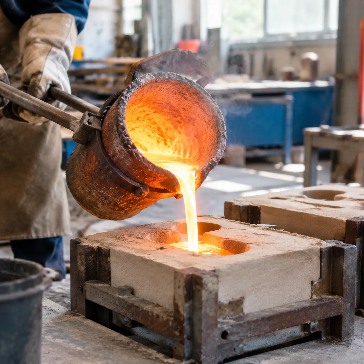
In expendable mold casting, we create a single-use mold that is destroyed to retrieve the solidified metal part. This casting method provides incredible geometric flexibility, making it the primary choice for everything from massive engine blocks to intricate jewelry.
Sand Casting for Heavy and Complex Metal Parts
Sand casting remains the workhorse of industrial manufacturing. By compacting a sand-binder mixture around a reusable pattern, we can pour virtually any alloy into molds of almost limitless size.
- Key Advantages: Lowest initial tooling cost, handles parts from a few ounces up to several tons, and works with both ferrous and non-ferrous alloys.
- Best Applications: Engine blocks, pump housings, machine bases, and heavy structural brackets.
- Trade-offs: Higher surface roughness and wider dimensional tolerances compared to metal-die methods.
When tackling custom geometries with short lead times, working with an experienced sand casting manufacturer for custom metal parts helps maintain tight dimensional control while keeping pattern costs low.
Investment Casting (Lost Wax) for High-Precision Components
Investment casting, or lost wax casting, produces complex, near-net-shape components with exceptional surface finishes. We inject wax into a metal die, assemble the wax patterns onto a central tree, coat them in a ceramic slurry, melt out the wax, and pour molten metal into the hardened ceramic shell.
- Key Advantages: Exceptional dimensional accuracy (±0.005 in/in), fine surface finishes (Ra 3.2 µm or better), and thin-wall capabilities.
- Best Applications: Turbine blades, aerospace brackets, medical implants, and high-performance valves.
- Key Resource: Reviewing an investment casting mold guide for precision parts helps optimize part design and runner layouts before tooling fabrication begins.
Shell Mold Casting for Smoother Surfaces and Tighter Tolerances
Shell mold casting refines basic sand casting by using resin-coated sand applied over a heated metal pattern. The heat cures the resin, forming a thin, rigid shell that joins to form a precise mold cavity.
- Better Surface Quality: The fine-grained resin sand delivers a smoother surface finish than traditional green sand.
- Higher Dimensional Stability: Thin, rigid shell walls reduce mold distortion during metal expansion.
- Typical Uses: Gear blanks, camshafts, transmission parts, and hydraulic valve bodies.
Plaster and Ceramic Mold Casting for Specialized Non-Ferrous Parts
For non-ferrous parts that demand sharp details and fine finishes without the expense of full investment casting tooling, plaster and ceramic mold processes provide an effective solution.
- Plaster Mold Casting: Uses a gypsum slurry mixed with additives to cast aluminum, zinc, and magnesium parts with smooth walls and fine details. Because plaster has low thermal conductivity, cooling is slow, which helps thin sections fill completely.
- Ceramic Mold Casting: Uses high-temperature refractory slurries that withstand high pouring temperatures, allowing precision casting of stainless steels and nickel-based superalloys.
| Casting Method | Typical Tolerance | Surface Roughness (Ra) | Best Metal Alloys | Ideal Production Volume |
|---|---|---|---|---|
| Sand Casting | ±0.5 mm to ±2.0 mm | 12.5 – 25 µm | Cast iron, steel, bronze, aluminum | Low to high |
| Investment Casting | ±0.1 mm to ±0.3 mm | 1.6 – 3.2 µm | Stainless steel, superalloys, aluminum | Low to medium-high |
| Shell Mold Casting | ±0.2 mm to ±0.5 mm | 3.2 – 6.3 µm | Cast iron, carbon steel, copper alloys | Medium to high |
| Plaster/Ceramic Mold | ±0.1 mm to ±0.4 mm | 1.6 – 3.2 µm | Aluminum, magnesium, tool steels | Low to medium |
Permanent Mold Casting Methods
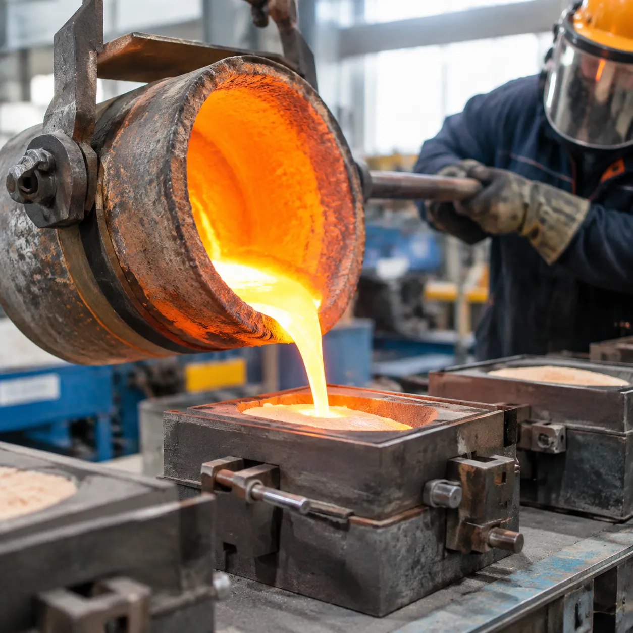
When production volume scales into the thousands and expendable molds become too slow or expensive, we turn to permanent tooling. A permanent mold casting method uses reusable dies machined from high-grade tool steel, iron, or graphite to deliver consistent dimensions, tight tolerances, and superior surface finishes cycle after cycle.
High-Pressure Die Casting for High-Volume, Thin-Walled Parts
High-pressure die casting (HPDC) forces molten alloy into hardened steel dies under extreme hydraulic pressure (often exceeding 1,000 bar).
- Best for: Complex, thin-walled aluminum, magnesium, and zinc components such as telecom chassis, power tool enclosures, and automotive transmission covers.
- Key advantage: Fast cycle times (seconds per part) and exceptional dimensional repeatability that minimizes post-machining.
- Trade-off: High upfront tooling investment; turbulent filling can trap air, making parts difficult to heat-treat.
For engineers deciding between metal mold formats, our aluminum alloy casting guide for die, sand, and investment methods breaks down the exact trade-offs across volume and alloy grades.
Gravity Die Casting for Strong Mechanical Properties
In gravity die casting (permanent mold casting), we pour liquid metal directly into a preheated steel mold using natural gravity to fill the cavity.
- Best for: Medium-to-high volume structural components like engine cylinder heads, brake calipers, and marine hardware.
- Key advantage: The slower, non-turbulent fill significantly reduces gas entrapment. Parts can undergo full heat treatment (such as T6) to achieve high tensile strength and elongation.
- Trade-off: Slower cycle times and thicker minimum wall requirements compared to high-pressure methods.
Low-Pressure Die Casting for Critical Automotive Parts
Low-pressure die casting (LPDC) uses a sealed holding furnace beneath the mold. Low-pressure gas pushes the melt upward through a riser tube into the die cavity from the bottom up.
- Best for: Safety-critical components, especially aluminum alloy wheels, suspension knuckles, and pressure-tight engine blocks.
- Key advantage: Smooth, bottom-to-top laminar filling virtually eliminates oxidation and slag inclusions, delivering dense, pore-free structural integrity.
- Yield efficiency: Minimal risers and runners mean significantly higher raw material yield.
Centrifugal Casting for Symmetrical, Hollow Cylindrical Shapes
Centrifugal casting relies on a high-speed rotating mold to distribute molten metal against outer walls using centripetal force.
- Best for: Pipes, bushings, engine cylinder liners, and large industrial rings.
- Key advantage: The high G-forces force denser, defect-free metal to the outside wall, while lighter impurities, oxides, and gas pockets float inward to the bore, where they are easily machined away.
- No cores required: Produces clean cylindrical interiors without complex interior sand cores.
Permanent Mold Casting Process Comparison
| Casting Method | Typical Pressure | Minimum Wall Thickness | Heat Treatable (T6) | Best Production Volume |
|---|---|---|---|---|
| High-Pressure Die Casting | 300 to 1,500+ bar | 1.0 – 1.5 mm | Limited / Specialized | 10,000+ units |
| Gravity Die Casting | Atmospheric | 3.0 – 4.0 mm | Yes | 1,000 to 50,000 units |
| Low-Pressure Die Casting | 0.2 to 1.5 bar | 2.5 – 3.5 mm | Yes | 5,000 to 100,000+ units |
| Centrifugal Casting | Centrifugal (up to 100 Gs) | 5.0+ mm | Yes | Low to High (Geometry dependent) |
How to Choose the Right Casting Method
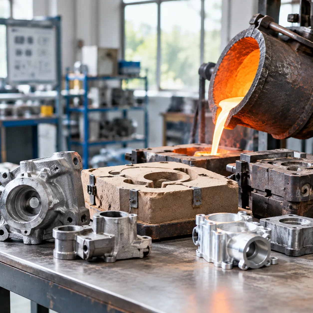
Selecting the right casting method comes down to balancing material properties, part complexity, budget, and delivery timelines. Every casting technique comes with distinct trade-offs between upfront tooling investment and part-to-part production speed.
Matching Metal Alloys to Casting Techniques
Not all alloys behave the same way in molten form. Pouring temperatures, thermal conductivity, and chemical reactivity dictate which casting technique will yield sound components:
- Ferrous Alloys (Steel, Cast Iron, Stainless Steel): Require refractory molds capable of withstanding extreme heat (>1,400°C / 2,550°F). Sand casting and investment casting handle these high-temperature metals best. For corrosion-resistant applications, selecting specialized cast stainless steel custom casting alloys and grades ensures the material retains its mechanical strength without mold erosion.
- Non-Ferrous Alloys (Aluminum, Zinc, Magnesium, Copper): Have lower melting points, making them ideal for reusable steel dies, permanent molds, and plaster casting.
Balancing Production Volume Against Tooling and Setup Costs
Upfront tooling expenditure dictates the per-unit economics of your project. High-volume runs justify hardened steel dies, while low-volume jobs benefit from pattern-based methods.
- Low Volume / Prototyping (1 to 500 parts): Sand casting and plaster mold casting offer minimal casting tooling cost and low initial risk.
- Medium Volume (500 to 5,000 parts): Investment casting and shell molding provide repeatable accuracy without extreme tooling overhead.
- High Volume (5,000+ parts): High-pressure die casting carries a significant upfront mold cost but delivers the lowest per-part manufacturing price and shortest cycle times.
To dial in your unit economics, consult our die casting vs sand casting cost, volume, and tolerance guide before committing to tooling.
Targeting Dimensional Accuracy, Wall Thickness, and Surface Finish
Your dimensional requirements determine whether secondary machining is necessary. Tighter as-cast tolerances eliminate excess cycle times and material scrap.
| Casting Method | Typical Dimensional Tolerance | Minimum Wall Thickness | Surface Roughness (Ra) |
|---|---|---|---|
| Sand Casting | ±0.5 mm to ±1.5 mm | 3.0 mm – 5.0 mm | 12.5 – 25 µm |
| Investment Casting | ±0.1 mm to ±0.3 mm | 1.0 mm – 1.5 mm | 1.6 – 3.2 µm |
| High-Pressure Die Casting | ±0.05 mm to ±0.15 mm | 0.8 mm – 1.2 mm | 0.8 – 1.6 µm |
| Gravity Die Casting | ±0.2 mm to ±0.4 mm | 2.5 mm – 3.0 mm | 3.2 – 6.3 µm |
Optimizing dimensional tolerance casting and achieving a low casting surface roughness directly reduces downstream grinding and polishing stages.
Post-Processing Requirements and Total Turnaround Time
A complete evaluation accounts for total lead time and post-cast operations:
- Machining Allowance: Tighter net-shape processes like investment and die casting need minimal machining stock (0.5 mm or less), whereas sand castings often require 2.0 mm to 4.0 mm of stock on critical mating faces.
- Thermal Treatment: High-strength structural parts need heat treatments (such as T5/T6 for aluminum or quench-and-temper for steel) to achieve target yield and tensile ratings.
- Time-to-Market: Sand casting patterns can be prepped in days, whereas precision multi-cavity die casting dies often require 4 to 8 weeks of tooling build time before production starts.
Common Casting Defects and How to Avoid Them
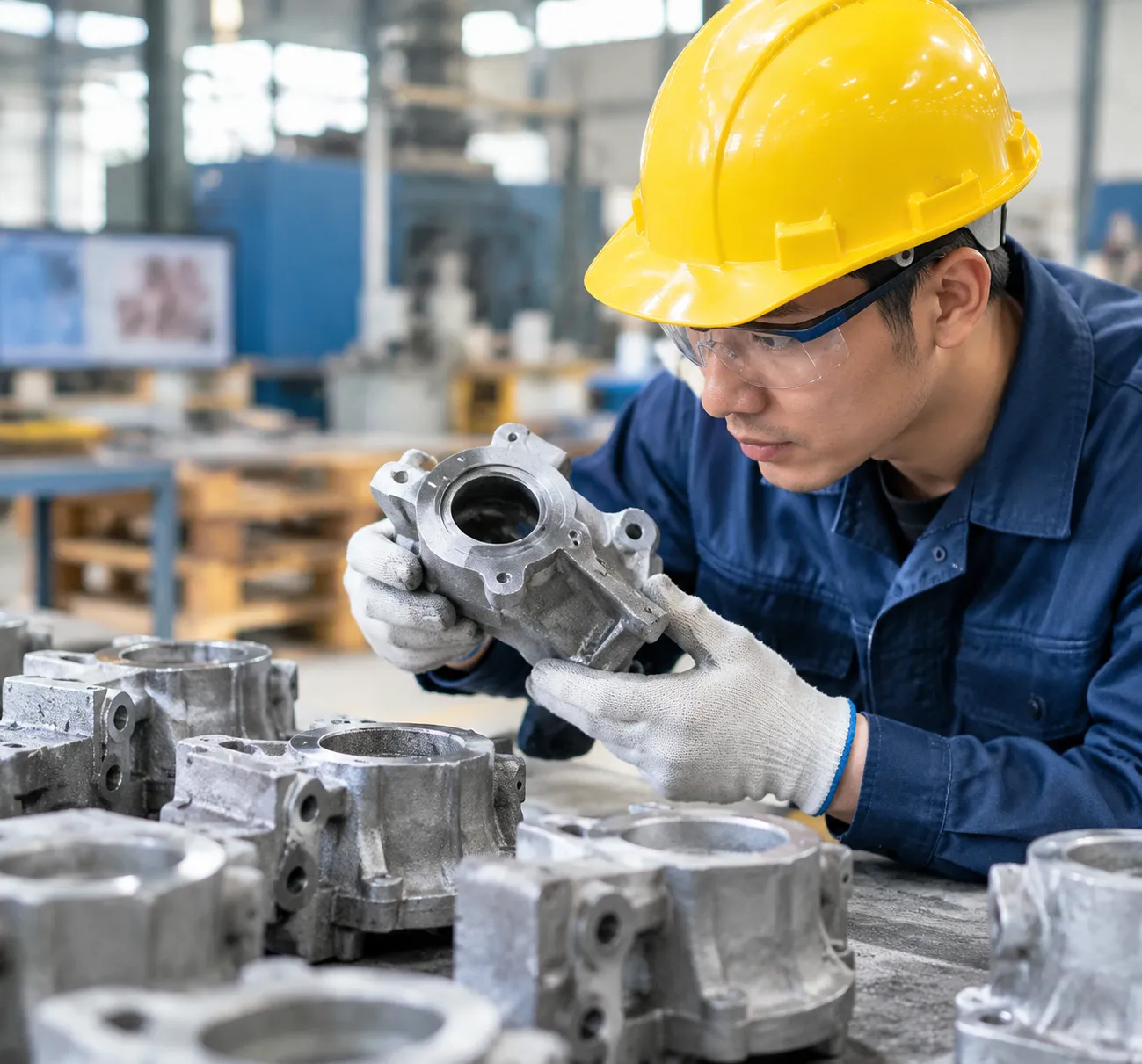
Even the most controlled casting method can encounter quality issues if process parameters shift. We focus on diagnosing metal casting defects early in the production cycle to eliminate scrap and maintain structural integrity.
Identifying Gas Porosity and Shrinkage Cavities
Internal voids weaken cast components and cause pressure-boundary failures. We isolate these into two primary root causes:
- Gas Porosity: Appears as smooth, rounded microscopic voids caused by trapped air, dissolved hydrogen, or mold outgassing during molten metal pouring. We eliminate this by degassing the melt, optimizing mold venting, and maintaining steady, non-turbulent pour speeds.
- Shrinkage Cavities: Irregular, angular voids that develop when metal contracts as it solidifies without sufficient liquid feeding. We prevent shrinkage by designing directional solidification patterns and sizing risers to feed thick sections continuously until fully set.
Preventing Misruns, Cold Shuts, and Slag Inclusions
Surface and filling defects compromise both aesthetics and load-bearing capacity:
| Defect Type | Root Cause | Preventive Action |
|---|---|---|
| Misrun | Metal freezes before completely filling the mold cavity. | Increase pouring temperatures, improve mold preheating, and reduce thin-wall travel distances. |
| Cold Shut | Two metal streams meet but fail to fuse due to premature cooling. | Optimize gating geometry to ensure rapid, unified metal flow. |
| Slag/Dross Inclusion | Non-metallic oxides or furnace dross enter the mold during pouring. | Utilize ceramic foam filters in the gating system and skim melts thoroughly before casting. |
Quality Testing with NDT, Radiography, and Dimensional Inspection
We rely on layered verification protocols to validate internal soundess and dimensional stability. Our production lines integrate non-destructive testing (NDT) alongside physical measurement tools to catch defects before shipping:
- Radiographic Testing (X-ray / RT): Delivers clear internal imaging to pinpoint subsurface gas pockets, shrinkage voids, and core shifts.
- Ultrasonic & Magnetic Particle Testing (UT / MPI): Detects internal cracks, laminar flaws, and surface-breaking discontinuities on ferromagnetic alloys. We apply these standards across our stainless steel sand casting services with complete NDT verification to verify high-stress structural parts.
- Dimensional & Coordinate Inspection (CMM / 3D Scanning): Compares physical castings directly against CAD models to confirm dimensional tolerance casting targets and critical machine stock allowances.
Frequently Asked Questions About Casting Methods
Which casting method produces the strongest metal parts?
Centrifugal casting and squeeze casting consistently deliver the highest tensile strength and density. Centrifugal force pushes impurities inward while compacting the outer wall, eliminating gas porosity. For complex structural shapes, high-pressure die casting and permanent mold casting also yield superior strength over sand casting due to rapid metal chilling and fine grain formation.
What is the most cost-effective casting process for low volumes?
Sand casting remains the most economical casting method for low production runs, prototypes, and large single-piece components. Pattern tooling costs are a fraction of the price of machined steel dies, and patterns can be quickly modified or 3D-printed without substantial capital investment.
| Casting Method | Tooling Cost | Ideal Batch Size | Unit Cost at Low Volume |
|---|---|---|---|
| Sand Casting | Very Low | 1 – 500 pcs | Low |
| Investment Casting | Moderate | 100 – 5,000 pcs | Moderate |
| Die Casting | Very High | 5,000+ pcs | High (due to tooling amortisation) |
What is the main difference between die casting and sand casting?
The fundamental difference lies in mold type and pressure. Die casting injects molten metal under extreme hydraulic pressure into reusable hardened steel dies, producing smooth, thin-walled, high-tolerance parts. Sand casting relies on gravity pouring into consumable silica sand molds, which accommodates higher melting point metals and massive component sizes.
For a comprehensive evaluation of tooling trade-offs, surface finish, and unit economics, check out our in-depth comparison of die casting vs sand casting.
Can all metals be cast using the same method?
No. Melting temperature, chemical reactivity, and fluidity determine which casting technique can safely process an alloy:
- Ferrous metals (Steel, Cast Iron): Require high-refractory molds like sand or ceramic shells because their high melting temperatures destroy permanent steel dies.
- Non-ferrous metals (Aluminum, Zinc, Magnesium): Well-suited for high-pressure die casting and permanent mold systems.
- Superalloys & Titanium: Require vacuum investment casting to prevent oxidation during molten metal pouring.
Selecting the right alloy and mold setup requires balancing thermal limits and budget, as detailed in our die casting vs investment casting cost and material guide.
How does cooling rate impact final grain structure and strength?
Cooling speed directly controls the microstructural grain size of cast metal:
- Fast cooling (Permanent molds & die casting): Promotes rapid nucleation, resulting in a fine, uniform grain structure that enhances mechanical hardness, yield strength, and fatigue resistance.
- Slow cooling (Sand & plaster molds): Allows grains to grow coarse and dendrites to expand, slightly reducing overall tensile strength but often improving machinability.
 English
  Russian
  German