
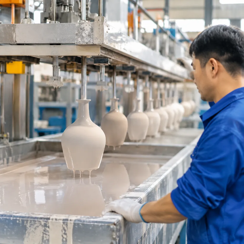
2026年11月9日
Learn steam dewaxing parameters and shell defect prevention with pressure control cycle timing and expert investment casting troubleshooting tips
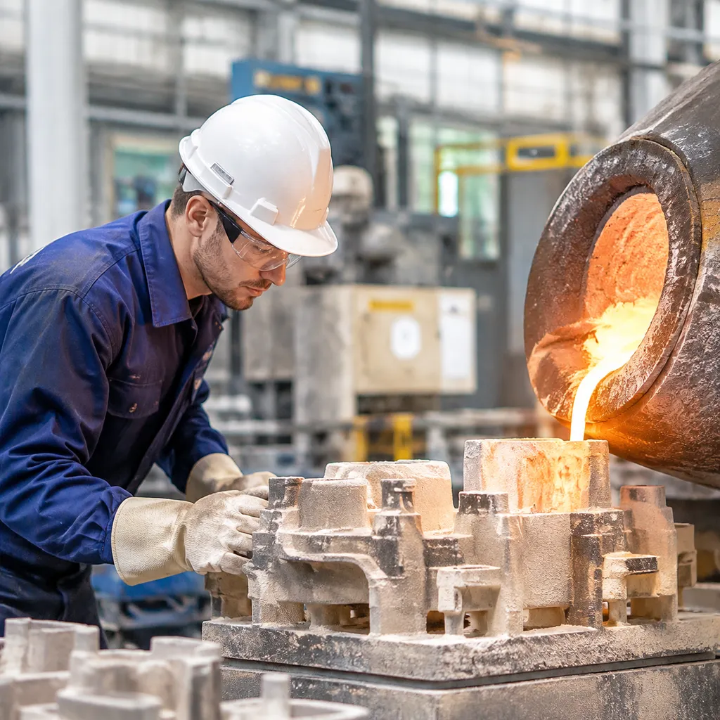
Core Mechanics: Why Steam Dewaxing Makes or Breaks Your Shells
Dewaxing is the most volatile stage in investment casting. In our foundry runs, an unoptimized cycle does not just cause minor flaws—it tears green shells apart before they ever reach the burnout furnace. Managing steam dewaxing parameters and shell defect prevention starts with understanding what happens inside that closed pressure vessel during the first few critical seconds.
How Flash Heating Protects the Ceramic Shell from Wax Expansion
Pattern wax expands violently when exposed to heat, while the surrounding ceramic shell remains rigid. To prevent the expanding pattern from shattering the mold, we rely on rapid heat transfer through saturated steam.
- Immediate surface melt: High-pressure steam creates instantaneous condensation on the shell exterior, conducting heat directly to the wax boundary layer.
- Volume relief: The outermost layer of wax melts into a liquid film in less than five seconds.
- Capillary drainage: As that boundary liquefies, it drains away through the gating system, creating an essential expansion gap before the core wax mass warms up and expands.
Physics of Wax Thermal Expansion vs Ceramic Shell Hoop Stress
The mechanical conflict during dewaxing boils down to a massive mismatch in the coefficient of thermal expansion (CTE). Pattern waxes expand significantly faster than colloidal silica-bonded ceramic refractories.
- The expansion gap: Unfilled pattern wax exhibits a volumetric thermal expansion of roughly 8% to 12% between room temperature and melting point. Ceramic shell systems expand by less than 1% across the same range.
- Hoop stress failure: If heat transfer is sluggish, bulk wax expands while still trapped in solid form. This creates extreme internal hoop stress against the concave surfaces and sharp interior radii of the shell.
- The failure limit: Once internal pressure exceeds the green modulus of rupture (MOR) of the ceramic shell—often hovering between 3.5 and 6.0 MPa—tensile failure occurs instantly, leading to longitudinal shell cracking.
| Property | Pattern Wax (Typical) | Ceramic Shell (Green) | Mechanical Impact |
|---|---|---|---|
| Volumetric Expansion | 8% to 12% | < 1% | Generates massive internal displacement |
| Thermal Conductivity | Low (insulator) | Moderate | Wax surface must melt before wax core heats |
| Tensile / Rupture Limit | Plastic yield | Low green MOR (3.5–6 MPa) | Shell cracks under hoop stress if not relieved |
Key Differences: Steam Autoclaves vs. Flash Fire Dewaxing
Choosing the right dewaxing platform dictates how you build your shells and balance your thermal budgets. We compare the operational realities below:
- Steam Autoclave Dewaxing: Uses pressurized saturated steam (6 to 8 bar) to transfer heat via rapid phase change condensation. The external pressure of the chamber helps counteract internal wax expansion forces while keeping temperatures uniform across dense pattern setups. Wax is fully recovered in clean, reusable condition without burning.
- Flash Fire Dewaxing: Relies on high-temperature atmospheric furnaces (800°C to 1000°C) to blast open the wax boundary layer through sheer thermal shock. While it eliminates the need for pressure vessels, it requires higher shell thermal shock resistance, risks incomplete wax evacuation on intricate parts, and consumes wax as fuel rather than allowing clean reclamation.
Controlling the initial burst of heat determines whether the pattern evacuates smoothly or splits your investment mold down the center. Consistent defect prevention requires precise control of that transition window.
Critical Steam Dewaxing Parameters You Must Control
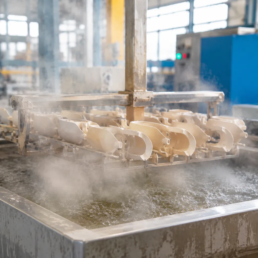
Dialing in your autoclave cycle comes down to a race against thermal expansion. If heat penetrates deep into the pattern before the surface melts and vents, the wax expands, generates severe hoop stress, and splits the mold wide open. Maintaining strict control over primary steam dewaxing parameters and shell defect prevention protocols requires setting tight operational boundaries on pressure, heat transfer, and timing.
| Parameter | Target Operating Window | Critical Failure Risk if Out of Spec |
|---|---|---|
| Pressurization Ramp Rate | 0 to 7–8 bar in < 7–10 seconds | Shell cracking from solid core wax expansion |
| Steam Temperature | 160°C to 180°C (saturated steam) | Incomplete boundary layer flash melting / superheated dry gas |
| Dewax Dwell Time | 10 to 15 minutes | Over-soaking ceramic binder or leaving unevacuated wax |
| Depressurization Rate | Controlled linear drop (30–45 seconds) | Explosive facecoat spalling from trapped steam |
| Accumulator Pressure | 10 to 12 bar (dedicated reserve) | Pressure lag during autoclave inlet valve opening |
Pressurization Ramp Speed: Hitting 6 to 8 Bar in Under 10 Seconds
The first ten seconds determine whether a mold survives. We run our steam dewaxing autoclave for fast wax removal to hit at least 6 to 8 bar within 7 to 10 seconds of valve actuation.
- The Mechanism: Instant steam pressure delivers immediate thermal shock to the wax skin right against the primary coat.
- The Goal: Liquefy a thin boundary layer of wax (roughly 0.5 to 1.0 mm) instantly.
- The Rule: If your ramp rate takes longer than 15 seconds, heat conducts into the bulk wax core. The core expands volumetrically while still solid, blowing out the green shell along part lines and sharp radii.
Operating Steam Temperature and Saturation Levels (160°C to 180°C)
Target saturated steam between 160°C and 180°C. Saturated steam provides a massive latent heat transfer coefficient compared to superheated dry steam or hot air.
- Avoid wet, low-pressure steam below 150°C; it condenses excessively, pooling water in the mold cavity that slows heat transfer and plugs wax drains.
- Avoid superheated steam; it behaves like dry gas, dropping the thermal transfer rate right at the pattern interface and causing delayed boundary melting.
Dwell Time Calibration: Balancing Wax Melt Against Shell Soaking
Once peak pressure is reached, hold the dwell time only as long as necessary to clear the patterns—typically between 10 and 15 minutes depending on cluster mass and sprue diameter.
- Under-dwelling (< 8 min): Leaves bulk wax inside thick sections, creating severe shell-firing blowouts during burnout.
- Over-dwelling (> 18 min): Saturates the porous colloidal silica or ethyl silicate binder with pressurized steam, degrading the green bond strength and inducing micro-fissures before handling.
Controlled Exhaust and Depressurization Rates
Never dump autoclave pressure instantaneously. While the pressurization must be near-instant, depressurization requires a metered, controlled exhaust over 30 to 45 seconds.
Ceramic shells are naturally porous and absorb steam during the soak. Dropping chamber pressure to atmospheric in 5 seconds creates a pressure differential between the inner shell wall and the chamber. The steam trapped inside the shell pores expands violently outward, causing inner facecoat delamination and surface spalling.
Steam Accumulator Volume Sizing for Zero-Lag Pressure Delivery
A standard boiler cannot generate steam fast enough to fill an autoclave chamber in under 10 seconds on its own. We eliminate pressure lag by running a dedicated steam accumulator directly upstream from the dewax vessel:
- Sizing Ratio: Size the accumulator vessel to at least 3 to 4 times the free volume of the loaded autoclave chamber.
- Pressure Differential: Charge the accumulator to 10–12 bar so that opening the main charging valve creates an immediate, massive pressure wave into the 7–8 bar operating chamber without pulling down main line boiler pressure.
Identifying Common Shell Defects from Improper Dewaxing

When our steam dewaxing process isn't dialed in, the ceramic shell pays the price. Understanding these failure modes is the first step toward reducing scrap rates in the investment casting process.
Here are the most common defects we see on the foundry floor when steam dewaxing parameters fail:
- Longitudinal and Radial Cracking: These fractures typically appear along sharp radii or junctions where the shell wall thickness changes abruptly. They are almost always caused by uneven heating or excessive hoop stress when the wax expands faster than the shell can accommodate.
- Facecoat Delamination and Spalling: If the pressure ramp is too slow or the steam penetration is inconsistent, the inner facecoat can lose its bond with the backup layers, leading to surface spalling that ruins casting finish.
- Green Shell Bursting: This is a violent failure caused by the bulk wax expanding before the surface wax has a chance to melt and drain. It usually happens when the autoclave pressure fails to reach the required threshold quickly enough.
- Distortion and Dimensional Creep: Thin-walled sections of the shell are prone to sagging or creeping if the autoclave temperature remains too high for too long, softening the green strength of the ceramic before the wax is fully evacuated.
- Ash Residue and Wax Inclusions: Poor wax evacuation, often caused by blocked drain lines or incorrect pattern orientation, leaves trapped wax or ash behind. This contamination directly impacts casting purity and leads to non-metallic inclusions in the final metal pour.
Upstream Shell Building and Pattern Prep to Prevent Cracking
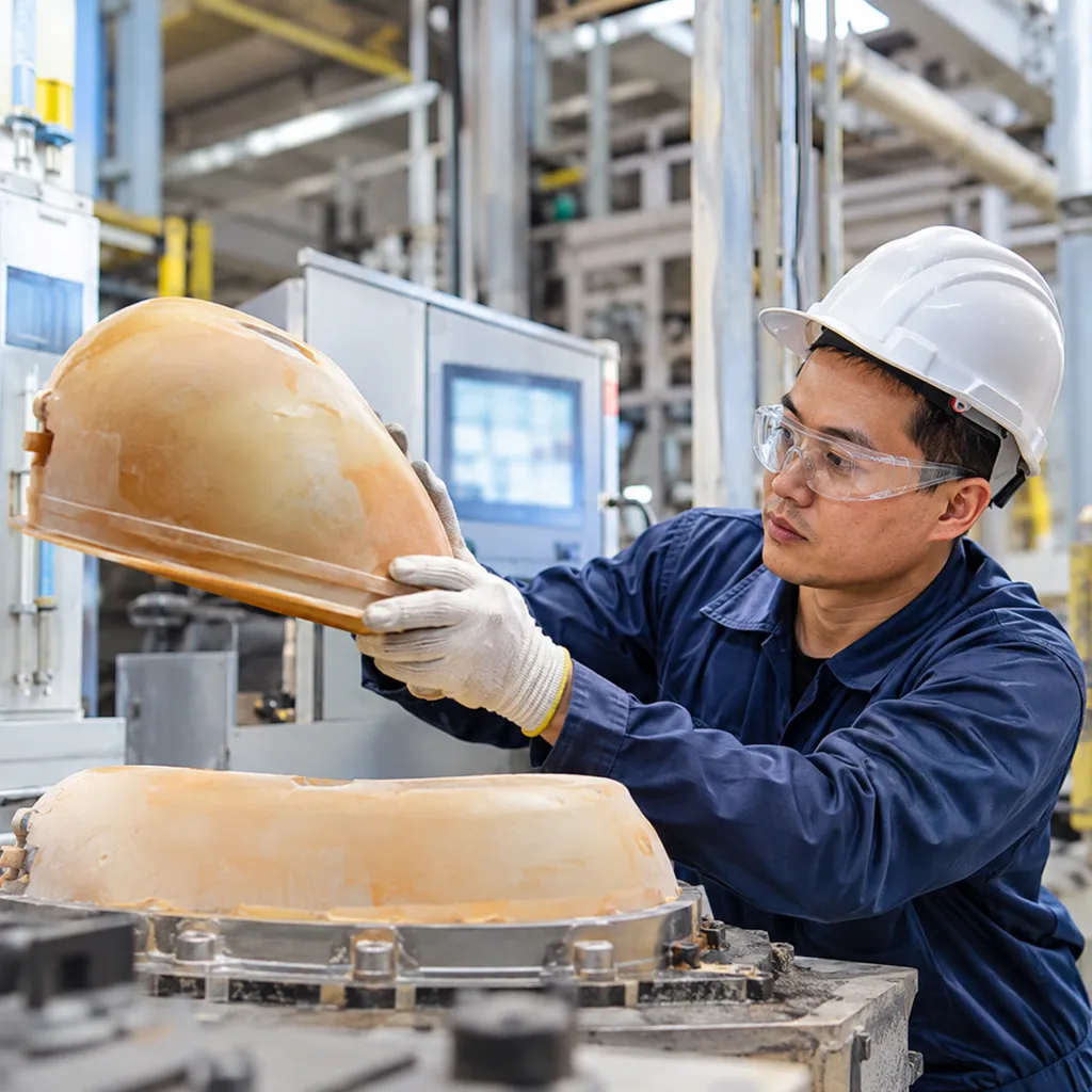
Autoclave settings mean nothing if your shell enters the chamber compromised. In our foundry, we treat dewax survivability as an upstream tooling and dipping challenge. If you do not give the expanding wax an escape route or build a shell capable of handling early mechanical stress, the mold will split before the steam reaches full temperature.
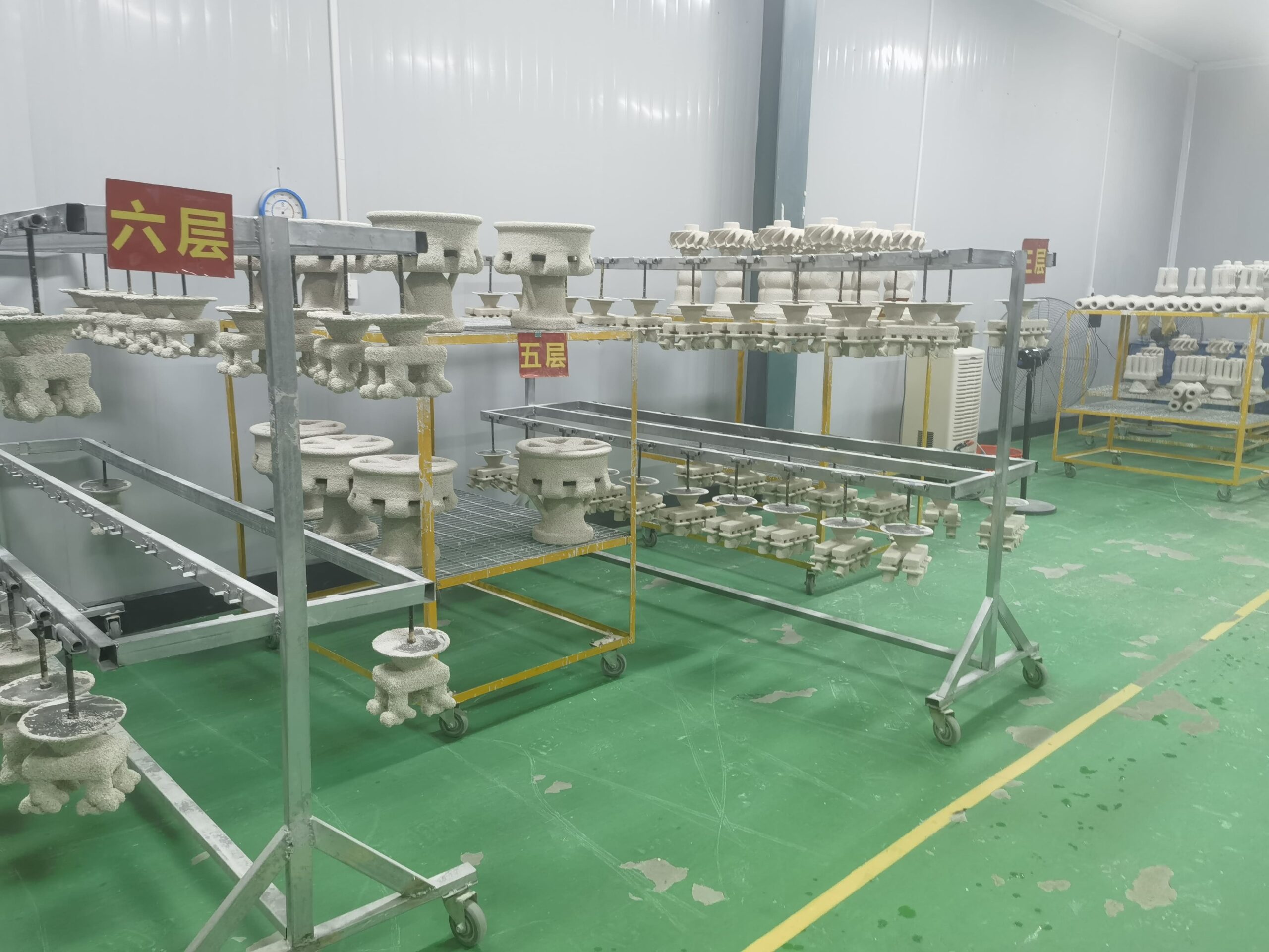
Optimizing Shell Permeability and Inter-Coat Drying
A green shell must breathe. When steam hits the mold, low green shell permeability traps internal steam pockets and volatile gases, spiking internal pressure before the wax evacuates.
- Maintain strict drying controls: We dry prime coats at 50% to 55% relative humidity and backup coats around 40% to 50% with adequate airflow. Undried moisture flashes into steam during dewaxing, blowing the coats apart from the inside.
- Control slurry viscosity: Excessively dense slurries choke slurry-stucco bonding. Standardizing your dipping cycles using automated ceramic shell coating dipping stuccoing drying systems ensures repeatable slurry thickness, proper refractory pack, and uniform porosity throughout every layer.
Reinforcing High-Stress Shell Zones with Structural Backup Coats
Ceramic shells naturally fail at sharp corners, internal radii, and re-entrant angles where hoop stress concentrates.
- Add patch dips: We manually or robotically apply targeted extra dips to known stress risers, runner junctions, and thick-to-thin transitions.
- Coarse stucco selection: Transition quickly from fine prime refractory (200-mesh flour) to coarser backup stucco (30/50 or 16/30 mesh fused silica or aluminosilicate). Coarse grains provide the structural mechanical interlock needed to absorb sudden radial expansion during the first critical seconds.
Modifying Pattern Wax Formulas: Filled Waxes vs Low-Expansion Blends
Your wax choice dictates how much expansion pressure the shell must survive.
| Wax Type | Volumetric Thermal Expansion (20°C to 100°C) | Green Shell Rupture Risk | Best Application Floor Use |
|---|---|---|---|
| Straight Unfilled Wax | 8.5% – 12.0% | High | Intricate thin-wall components; requires ultra-fast steam ramps |
| Polymer-Filled Wax | 4.5% – 6.5% | Low | Heavy cross-sections, structural engineering castings |
| Emulsified (Water-Filled) Wax | 5.0% – 7.0% | Moderate | General commercial castings; good dimensional stability |
Filled waxes replace raw hydrocarbon volume with inert polymeric fillers. Because the filler does not expand thermally at the same rate, total volumetric expansion drops significantly, keeping stresses below the shell's modulus of rupture.
Adding Weep Holes, Pattern Vents, and Relief Cuts
Thick wax sections expand faster than heat can liquefy them through to the core. We neutralize this bulk hydraulic expansion by modifying the pattern assembly:
- Drill weep holes: Placed directly at the base of heavy runners or pour cups to let liquefied facecoat wax exhaust instantly into the autoclave floor.
- Insert hollow pattern vents: Run soluble or wax-extruded hollow cords through massive chunks. The core yields inward into the hollow void instead of pressing outward against the ceramic wall.
- Carve internal expansion relief cuts: On massive blind pockets, saw-kerf relief grooves into the wax patterns before final assembly, giving the expanding material a path of least resistance.
Autoclave Setup, Monitoring, and Maintenance Best Practices
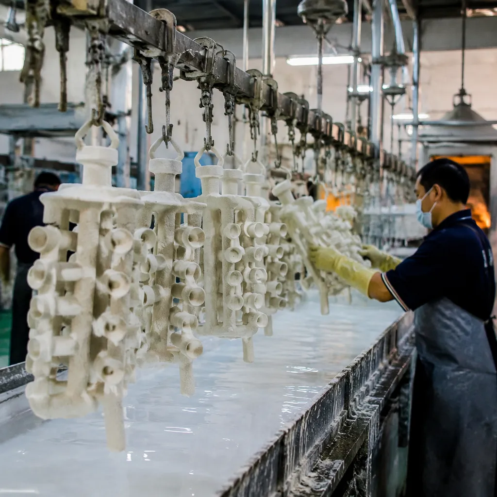
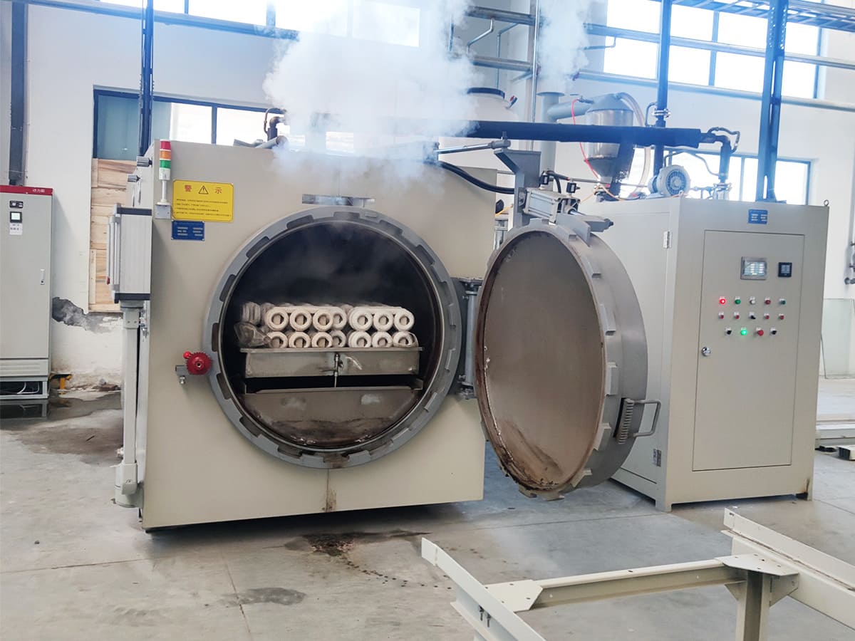
Consistent steam dewaxing requires rigorous machine maintenance. Even a two-second delay during steam pressurization will blow apart green shells. We keep our autoclave hardware dialed in using standard mechanical setups, strict sensor checks, and clean wax run-off lines to prevent scrap runs.
Sizing Pneumatic Quick-Actuating Bypass Valves for Rapid Entry
Standard process valves open too slowly to deliver the thermal shock needed for flash dewaxing. You need dedicated, fast-acting pneumatic bypass valves designed for saturated steam service.
- Valve Style: High-flow, full-bore pneumatic ball or angle-seat valves.
- Actuation Speed: Must fully open from 0% to 100% in under 1.5 seconds.
- Port Sizing: Never size down from the steam accumulator supply line. If your accumulator header is 3 inches (DN80), your main injection valve must be at least 3 inches. Restricting the flow profile creates downstream pressure drops that destroy your pressurization curve.
- Air Supply Backup: Install a dedicated local pneumatic accumulator tank on the valve actuator air line so drops in main shop air pressure never slow down valve stroke times.
Preventing Drain Line Blockages from Solidified Wax Buildup
A plugged wax drain creates immediate backpressure, traps liquid wax inside the shell cavity, and causes hydrostatic mold failure.
- Steam Tracing: Wrap all wax exhaust plumbing, blowdown legs, and collector valves with continuous steam tracing or high-wattage electric jacket heaters set to 110°C–120°C (230°F–248°F).
- Slope and Gravity: Run all bottom drain manifolds on a minimum 15-degree downward pitch directly into the wax recovery tank. Avoid horizontal runs longer than 12 inches.
- Automated Flush Cycles: Program a 3- to 5-second high-pressure steam blowdown at the end of every dewax cycle to purge residual wax droplets from the seat surfaces before they solidify.
Routine Sensor Calibration for Chamber Pressure and Steam Quality
If your instruments are off by even 0.5 bar, your cycle parameters are out of control. We cross-verify mechanical gauges and electronic transmitters weekly.
| Component | Inspection Frequency | Operational Standard | Action on Deviation |
|---|---|---|---|
| Pressure Transducers | Bi-weekly | Dual-channel matched within ±0.05 bar | Recalibrate or replace sensor immediately |
| Chamber RTD Probes | Monthly | Match saturated steam table (±1°C) | Replace probe; inspect for wax coating |
| Steam Separators | Weekly | Zero liquid carryover at autoclave inlet | Service mechanical float traps |
| Exhaust Mufflers | Weekly | Free flow without pressure back-buildup | Soak in solvent tank to strip wax vapor |
Establishing Real-Time Pressure-Drop Alarms and Cycle Logging
Digital cycle monitoring catches mechanical faults before you lose an entire rack of assemblies. We track pressure curves millisecond by millisecond to maintain casting quality standards for reliable metal parts.
- Ramp-Rate Interlocks: Set an automated PLC abort threshold. If the chamber fails to reach 6 bar within 8 to 10 seconds of valve actuation, trigger a visual/audible alarm and flag the batch for non-destructive inspection.
- Pressure-Drop Thresholds: Monitor steady-state dwell. A drop exceeding 0.3 bar during the hold period indicates door seal leakage, stuck exhaust seats, or insufficient accumulator volume.
- Data Historian Logging: Log every single run with timestamps, peak ramp speeds, soak temperatures, and exhaust drop times. Comparing cycle curves across production shifts is the fastest way to pinpoint wear on valves and seals before catastrophic shell cracking occurs.
Frequently Asked Questions: Steam Dewaxing Parameters and Shell Defect Prevention
What is the absolute maximum pressurization time allowed to prevent cracking?
We keep autoclave pressurization under 10 seconds, with an optimal target between 4 and 7 seconds to reach 6 to 8 bar.
If your pressurization ramp rate drags past 10 to 12 seconds, you lose the flash-melting effect. Instead of liquefying a microscopic outer boundary layer to relieve pressure, heat conducts deep into the bulk wax. The solid core expands thermally, generating hoop stress that exceeds green shell tensile strength and splits the ceramic mold wide open. Fast valve actuation and dedicated accumulator storage in our dewaxing autoclave systems ensure you achieve this instant pressure rise without lag.
Why are green shells cracking even when autoclave pressure reads normal?
Hitting your target bar rating does not guarantee a clean dewax. When shells fail under normal gauge readings, look for these hidden triggers:
- Wet steam delivery: Low steam quality carries condensate into the chamber, cooling the shell surface instead of delivering rapid latent heat.
- Clogged drain lines: Solidified wax buildup in the bottom exhaust chokes flow, trapping expanding liquid wax inside the cluster.
- Low green shell permeability: Backup coats dried with excessive colloidal silica form an impermeable barrier, trapping moisture that boils into high-pressure steam within the shell wall.
- Unvented thermal masses: Heavy hubs or thick wax bosses lack pattern weep holes, forcing thermal expansion directly against sharp inside corners. We break down these mechanical failures further in our detailed review of shell cracking causes in investment casting explained.
How does relative humidity during shell drying impact dewaxing survivability?
Relative humidity (RH) directly controls the green strength and residual moisture of your ceramic mold before it ever enters the autoclave:
| Drying Room Condition | Shell Impact at Dewaxing | Primary Defect |
|---|---|---|
| High RH (>70%) | Backup coats retain structural water; slurry binders fail to cross-link fully. | Explosive internal steam spalling and catastrophic shell burst. |
| Optimal RH (45%–55%) | Uniform binder gelation; controlled green permeability and peak bond strength. | Clean wax boundary release with zero structural delamination. |
| Low RH (<35%) | Accelerated surface skinning; stresses build between primary and backup layers. | Facecoat delamination and fine hairline fissures prior to autoclave entry. |
Can you salvage a ceramic shell with hairline dewax cracks before burnout?
In 95% of cases, do not try to patch a dewax crack.
Patching slurries do not bridge fine cracks through the full wall thickness. Once molten alloy hits the defect during pouring, ferrostatic pressure will burst the patch, resulting in runouts or severe metal finning.
If a crack is purely superficial and limited to an outer backup coat: 1. Butter the crack using high-viscosity zircon slurry blended with ceramic binder. 2. Wrap the affected area tightly with ceramic fiber tape. 3. Slurry and stucco an extra patch layer over the tape before firing.
Foundry rule of thumb: If the crack extends to the primary facecoat or runs along a sharp part radius, scrap the cluster immediately.
What wax properties cause the highest risk of shell failure during dewaxing?
The most hazardous wax characteristics on the foundry floor are:
- High volumetric expansion: Straight, unfilled paraffin waxes expand 8% to 10% by volume between room temperature and 70°C.
- Broad melting ranges: Blends that soften gradually over a wide temperature span expand aggressively while retaining enough mechanical stiffness to break ceramic walls.
- Low thermal conductivity: Wax that resists surface heat absorption delays the formation of a fluid slip layer at the ceramic interface.
To protect vulnerable shells, switch to pattern waxes filled with 15% to 30% cross-linked polymers or organic fillers. Fillers displace raw wax volume and bring net thermal expansion down to a manageable 4% to 6%.
 English
 Russian
 German