

2026年11月5日
Learn the main shell cracking causes in investment casting and discover practical ways to prevent defects and improve casting quality
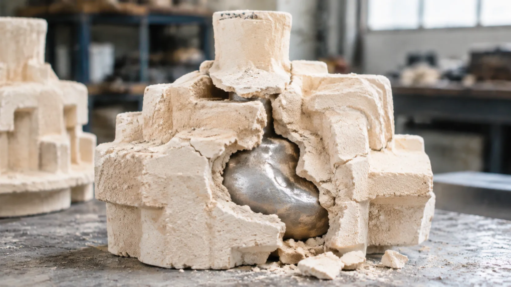
Primary Stages Where Shell Cracking Occurs
In our experience, identifying shell cracking causes in investment casting requires a systematic analysis of the three critical thermal stages. Each phase imposes specific mechanical and thermodynamic stresses that, if not managed, lead to catastrophic shell failure.
Dewaxing Stage Risks and Wax Thermal Expansion
The dewaxing process is the most frequent point of failure. Because wax patterns have a significantly higher coefficient of thermal expansion than ceramic shell materials, the wax exerts extreme internal pressure against the shell walls as it heats. If the shell lacks sufficient green strength or if the autoclave steam pressure builds too slowly, the expanding wax volume fractures the ceramic before the wax can melt and escape. Rapid, uniform heat transfer is essential to ensure the inner boundary of the wax liquefies immediately upon contact with the heat source.
Sintering Phase Thermal Gradients
During the firing or sintering process, the shell undergoes a transition that stabilizes the ceramic bond. Cracking here is often driven by internal thermal gradients. If the heating rate is too aggressive, the exterior of the shell expands or shrinks at a different rate than the interior, creating severe shear stress. Furthermore, variations in shell density—caused by inconsistent refractory layering—lead to uneven sintering shrinkage, which pulls the shell apart at density transition points.
Pouring Stage Stress Factors
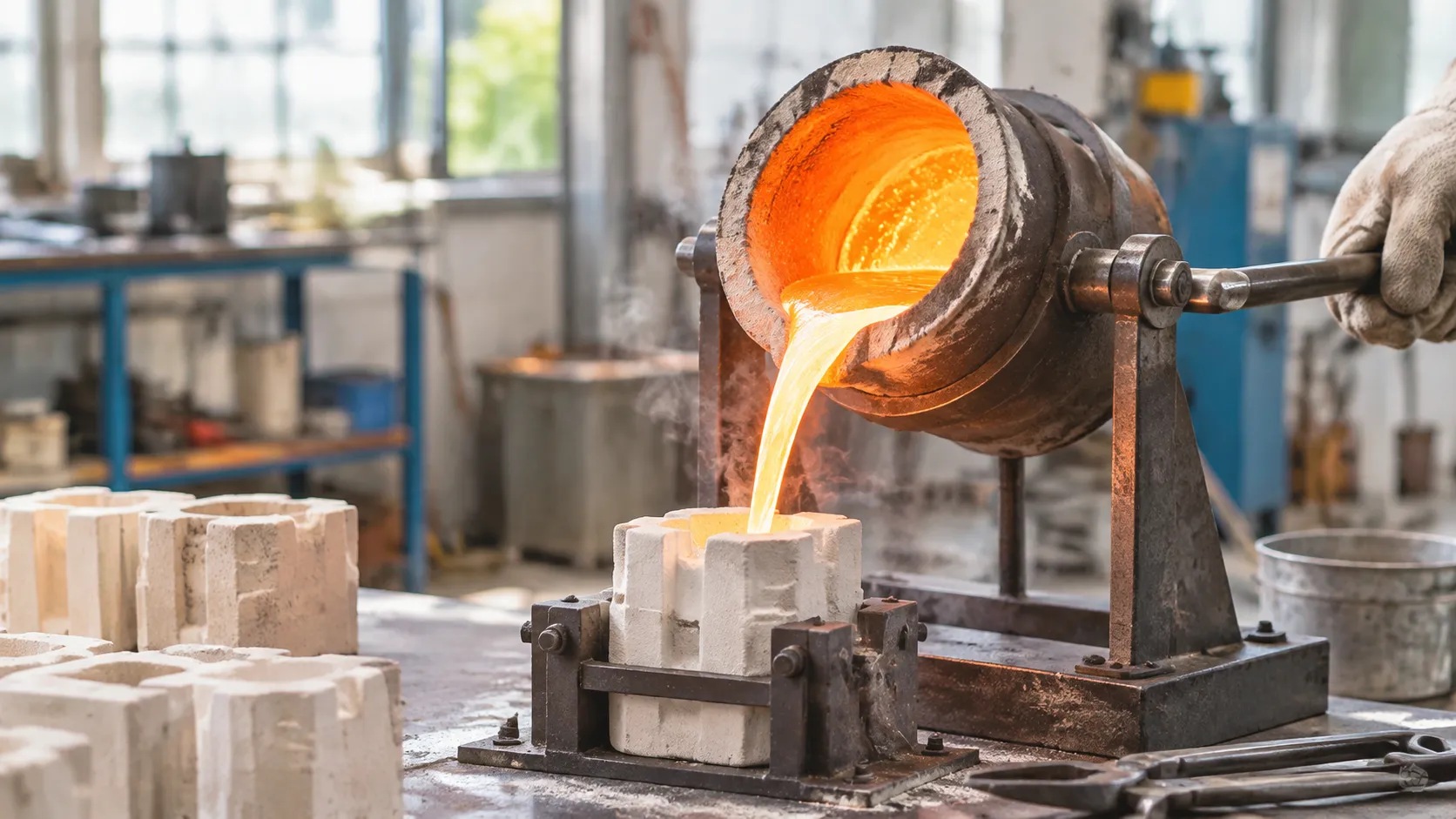
When molten metal enters the shell, it introduces a combination of intense thermal shock and mechanical force. Shell cracking causes in investment casting during this final phase are typically linked to: Metallostatic Pressure: The weight of the molten metal can exceed the shell’s hot modulus of rupture (MOR), causing walls to bulge or rupture. Thermal Shock: The rapid temperature spike upon contact with molten metal can instantly exceed the ceramic's fracture toughness. Structural Mismatch: Differences in the thermal expansion coefficients between the prime coat and the backup layers often result in delamination or cracking when subjected to the heat of the pour.
Core Technical Causes of Shell Cracking in Investment Casting
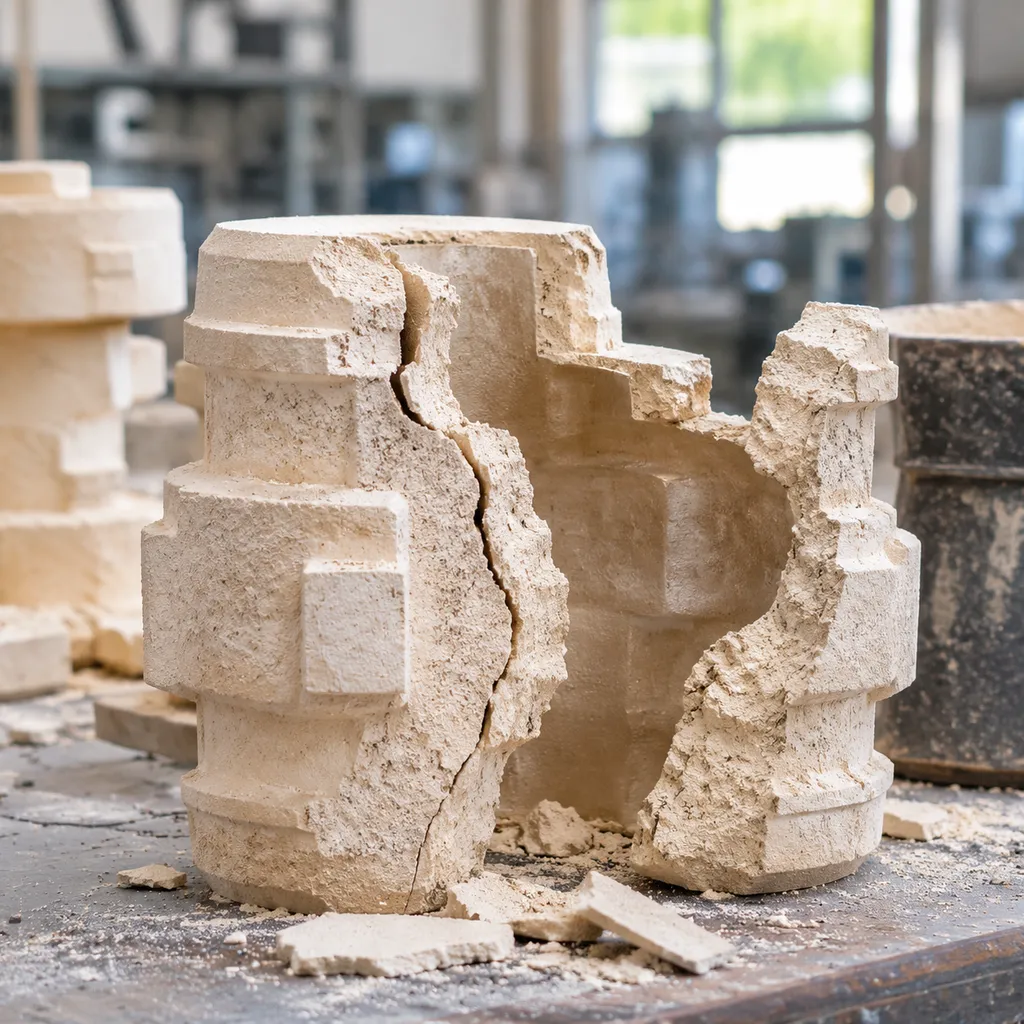
Identifying the root shell cracking causes in investment casting requires evaluating how slurry properties, drying environments, and part geometry interact. When these variables fall out of balance, the ceramic mold loses structural integrity long before pouring.
Binder Chemistry and Silica Sol Grain Distribution
The binder forms the structural backbone of the mold. In our foundry operations, silica sol stability dictates initial green strength and high-temperature performance:
- Silica Content Fluctuations: If the silica concentration drops below 30%, inter-particle bonding weakens, leaving the shell prone to brittle failure.
- pH and Gelation Control: Silica sol binders destabilize if pH levels drift outside the 9.0 to 10.0 window, leading to premature gelation, uneven slurry distribution, and micro-cracking across prime coats.
- Refractory Loading: An unbalanced slurry refractory ratio generates voids between fused silica or zircon flour particles. When optimizing our precision casting solution with silica sol process, we maintain exact slurry viscosity to ensure dense refractory packing.
Drying Kinetics, Relative Humidity, and Airflow Balance
Improper drying is one of the most frequent shell cracking causes in investment casting:
- Rapid Surface Skinning: High airflow (>3 m/s) paired with relative humidity (RH) below 45% dries the outer layer too quickly. The skin contracts over a wet substrate, inducing tensile stresses that trigger map cracking.
- Moisture Entrapment: Insufficient drying time or RH above 75% on backup coats traps free water. During autoclave dewaxing, trapped water vaporizes, expanding rapidly and rupturing the shell walls.
- Thermal Gradients: Inconsistent ambient temperatures cause localized shrinkage differentials across flat sections.
Part Geometry, Sharp Radii, and Stress Concentration Points
Component design directly influences thermal and mechanical stress distribution in the ceramic shell:
- Sharp Internal Corners: Fillets below R1.5 mm act as severe stress risers. Expanding pattern wax concentrates mechanical force directly against these tight radii.
- Abrupt Wall Thickness Transitions: Moving abruptly from thick to thin cross-sections creates differential cooling rates, generating residual shear stress in the ceramic matrix.
- Core Trapping: Deep, narrow pockets restrict wax drain paths, multiplying hydrostatic pressure during the melt cycle.
Stucco Grain Size Gradation and Coat-to-Coat Adhesion Failure
Grading the stucco sand correctly ensures stress transfers uniformly through the laminate thickness:
- Improper Mesh Sequencing: Jumping abruptly from fine prime stucco (e.g., 80–120 mesh) to coarse backup materials (e.g., 16–30 mesh) causes mechanical interlock failure and coat delamination.
- Excessive Dust Accumulation: Unscreened stucco creates dry powder pockets on wet slurry coats, preventing binder penetration and forming planes of weakness.
- Over-Dewetting: Inadequate wetting agent content prevents backup slurries from penetrating the underlying stucco voids, reducing overall hot modulus of rupture (MOR).
| Process Parameter | Defect Mechanism | Target Operating Window |
|---|---|---|
| Slurry pH | Premature gelation and binder brittleness | 9.2 – 9.8 |
| Drying Room RH (Backup coats) | Incomplete core drying; steam ruptures | 50% – 60% |
| Drying Room Airflow | Non-uniform surface shrinkage and cracking | 1.0 – 2.0 m/s |
| Internal Corner Radii | Mechanical stress concentration from wax | ≥ R2.0 – R3.0 mm |
| Stucco Mesh Progression | Interlaminar shear and spalling | Stepwise (100-mesh → 50-mesh → 30-mesh) |
Actionable Engineering Solutions to Prevent Shell Cracking
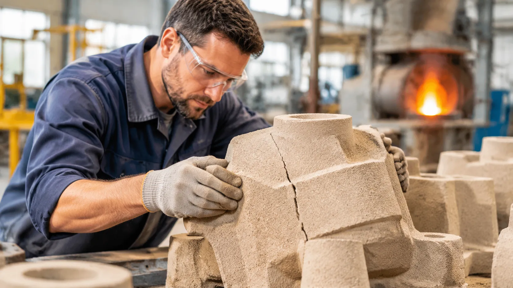
Eliminating shell cracking causes in investment casting requires systematic process adjustments on the foundry floor. When ceramic shell failure drives up scrap rates, our engineers target three primary intervention zones: dewaxing kinetics, mechanical strength benchmarking, and structural reinforcement of the backup coats.
Optimizing Autoclave Dewaxing Cycles and Steam Pressurization Rates
Wax thermal expansion happens significantly faster than shell thermal expansion. To prevent the pattern from expanding outward and rupturing the green ceramic, you must melt the outer wax layer instantly.
- Rapid Pressurization Target: Ramp boiler pressure to operating levels (7 to 8 bar / 100 to 115 psi) in under 10 seconds. Any delay allows pattern heat transfer before the outer shell interface liquefies.
- Accumulator Capacity: Ensure steam accumulators maintain adequate reserve volume. A drop in initial steam velocity during cycle start directly triggers radial stress cracks.
- Bypass and Exhaust Calibration: Keep exhaust valves fully sealed during initial pressurization, then purge rapidly once the melt boundary forms. Upgrading your foundry's dewaxing autoclave system to support automated steam bypass prevents thermal stalls that fracture delicate ceramic clusters.
Benchmarking Green MOR and Hot MOR Baseline Thresholds
We continuously monitor the Modulus of Rupture (MOR) across production batches to verify that shell layers can withstand both mechanical dewaxing stresses and thermal shock during metal pouring.
| Performance Metric | Target Baseline Threshold | Primary Failure Risk if Sub-Standard |
|---|---|---|
| Green MOR (Room Temp) | ≥ 4.5 to 6.0 MPa | Shell rupture and longitudinal cracking during autoclave dewaxing |
| Hot MOR (1000°C Fired) | ≥ 8.0 to 12.0 MPa | Bulging, finning, and run-outs under metallostatic pressure |
| Shell Permeability | 2.5 to 4.5 nPerm | Trapped gas expansion leading to prime coat spalling and micro-cracking |
Calibrate slurry solids loading and binder concentrations weekly. If green MOR drops below baseline, check the dipping room drying curves before modifying core chemical formulas.
Reinforcing Ceramic Shells with Structural Fibers and Optimized Backup Layers
To improve structural resistance against lost-wax casting defects without dramatically increasing shell wall thickness, we reinforce the intermediate and backup dipping slurries:
- Incorporate Organic Reinforcing Fibers: Blend short nylon or polypropylene microfibers (0.1% to 0.3% by weight) into secondary and backup slurries. These fibers create a mechanical interlock that absorbs expansion stresses during dewaxing, then burn out cleanly during preheat firing.
- Step-Down Stucco Gradation: Avoid stark transitions between grain sizes. Transition progressively from fine primary stucco (e.g., 80/120 mesh fused silica) to intermediate (50/100 mesh) and coarse backup grains (30/50 or 16/30 mesh). Uniform grading prevents interlaminar shear failure.
- Add Targeted Wrap Coats: For parts with deep pockets or sharp interior corners, apply manual localized patch dips or additional backup wraps along known stress-concentration axes to balance shell compliance.
Best Practices for Foundry Quality Assurance and Slurry Control

Controlling slurry properties and room climate prevents structural weaknesses before ceramic shells ever reach the dewaxing furnace or pouring line. We eliminate root shell cracking causes in investment casting by enforcing tight environmental metrics and structured inspection gates across every coat cycle.
Regulating Dipping Room Temperature and Relative Humidity Parameters
Uncontrolled drying causes differential shrinkage between prime and backup coats, resulting in micro-fractures. We balance airflow, relative humidity (RH), and temperature to guarantee uniform moisture removal across complex part geometries.
| Process Variable | Target Specification | Impact on Shell Integrity |
|---|---|---|
| Prime Coat Temperature | 20°C – 22°C (68°F – 72°F) | Prevents thermal pattern expansion and initial coat stress |
| Prime Coat Humidity | 50% – 55% RH | Slows initial dry rate to eliminate surface crazing |
| Backup Coat Humidity | 40% – 45% RH | Accelerates binder gelation without surface skinning |
| Airflow Velocity | 0.5 – 1.5 m/s across racks | Eliminates wet pockets in recessed geometries |
| Slurry Viscosity (Zahn #4) | Checked every 4 hours (±1 sec) | Maintains planned layer thickness and prevents coat lifting |
By aligning room climate with rigorous casting quality standards for reliable metal parts, our technicians prevent moisture pockets that burst during subsequent thermal cycles.
Standardizing Visual Inspection and Non-Destructive Testing (NDT) Workflows
Catastrophic mold failure during pouring usually stems from sub-surface flaws that go unnoticed during dipping. We deploy non-destructive testing (NDT) workflows to flag compromised shells before metal delivery:
- High-Intensity Optical Inspection: We audit shells under targeted LED lighting after prime-coat drying to flag bridging, voids, and edge thinning at sharp internal radii.
- Acoustic Ring Testing: Light tapping on fired shells helps our operators instantly identify delamination between backup layers based on pitch changes.
- Fluorescent Penetrant Screening: We conduct localized penetrant checks on sacrificial test shells from high-stress production batches to isolate microscopic fracture paths around heavy wax junctions.
- Pre-Pour Visual Audits: We inspect shells immediately after preheat firing to scrap any molds displaying thermal shock fissures before they reach the pouring floor.
Frequently Asked Questions About Shell Cracking in Investment Casting
Why does a ceramic shell crack during autoclave dewaxing?
The primary driver is volumetric thermal expansion mismatch between pattern wax and the refractory shell. Wax expands at a rate nearly ten times higher than ceramic when exposed to heat. If your autoclave fails to ramp up steam pressure quickly enough, heat penetrates the wax pattern before the thin surface boundary can liquefy and vent. The expanding wax creates massive hoop stress, leading to green shell ruptures along mold seams and sharp geometries.
To prevent this defect, we implement the following operational baselines: Pressurization speed: Bring the autoclave to full working pressure (8 to 10 bar) within 10 to 12 seconds. This rapidly melts the wax interface layer and creates expansion relief space. Green strength optimization: Maintain a consistent slurry refractory ratio and adequate binder solids to ensure sufficient unfired green modulus of rupture (MOR). Venting features: Add bleed holes or wax vents on heavy sections to alleviate local hydrostatic pressure.
How do you calculate the optimal drying time between slurry coats?
We never rely on arbitrary time schedules because ambient swings in relative humidity (RH) and temperature directly distort evaporation kinetics. Instead, we calculate drying completion through residual moisture loss and controlled environmental metrics:
- Weight loss monitoring: A dip layer is ready for the next coat only after it sheds 90% to 95% of its free moisture. Tracking sample weight on the drying line provides an exact threshold.
- Climate parameter control: Maintain drying room conditions at 20°C to 25°C, relative humidity at 50% to 60%, and laminar airflow at 1.5 to 3.0 m/s.
- Automation consistency: Running parts through an automatic shell coating line for investment casting eliminates uneven coat drying by locking in consistent dwell times and uniform airflow across every cluster.
Under-dried inner layers retain water that boils and explodes during autoclave dewaxing, while over-dried coats suffer from poor coat-to-coat bonding, both of which are common shell cracking causes in investment casting.
Does ceramic shell permeability directly impact cracking risk?
Yes. Shell permeability directly governs how quickly expanding gases escape during both dewaxing and pouring.
When molten metal hits the mold, residual volatile compounds instantly gasify. If the ceramic matrix is too dense due to excessive fine flour or improper slurry formulation, internal gas pressure spikes instantly. Combined with metallostatic pressure and thermal shock loads, this trapped gas fractures the mold walls, triggering metal run-outs and casting scrap.
Our technicians balance permeability without sacrificing hot MOR by managing refractory grain sizing: Stucco distribution: Use coarser, well-graded stucco on backup layers to build an interconnected pore network. Organic burnout additives: Introduce temporary polymeric burnout fibers into intermediate coats to leave micro-channels after the firing stage. Binder control: Avoid over-concentrated colloidal silica mixes that seal off the ceramic shell surface and restrict air evacuation during the pour.
 English
 Russian
 German