
2026年11月10日
Foundry Robot Integration Checklist with setup steps safety checks and performance tips for reliable efficient robotic foundry automation
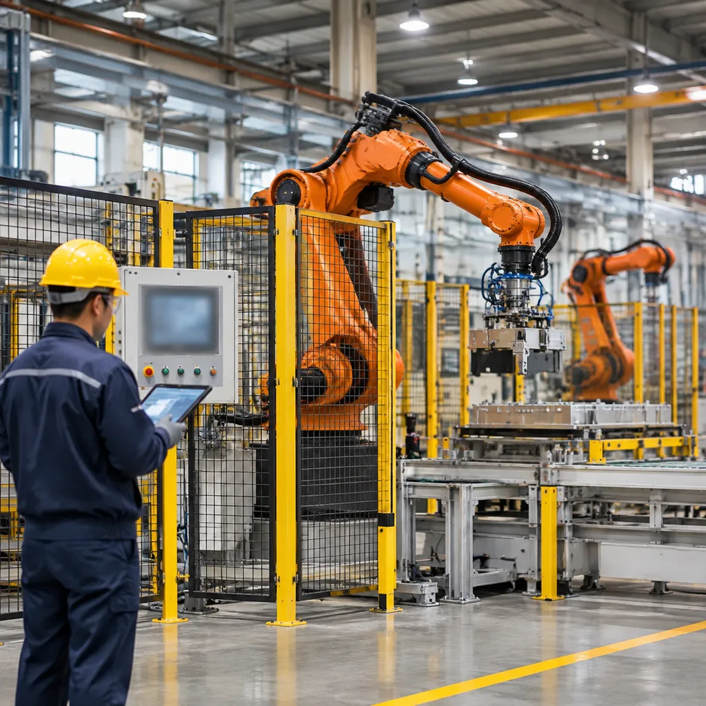
Pre-Integration Facility Audit
Before deploying robotic systems into a high-output environment, we conduct a rigorous facility audit to ensure your infrastructure supports sustained automation. Integrating a foundry robot integration checklist begins with validating the physical and environmental integrity of the shop floor.
Site Assessment Criteria
- Space and Capacity: Evaluate available floor space to accommodate robot reach and safety perimeters. Confirm concrete thickness and structural load capacity to ensure the robot base remains stable during high-speed, high-torque casting extraction.
- Environmental Factors: Document ambient temperature spikes, particulate dust density, and potential electromagnetic interference (EMI) sources that could impact sensor reliability or controller performance.
- Utility Requirements: Audit the stability of the electrical supply to prevent voltage drops. Verify compressed air pressure consistency and flow rate of cooling water lines essential for equipment thermal management.
- Workflow Mapping: Precisely map upstream and downstream casting process dependencies. Analyze the movement of raw materials and finished goods to minimize cycle-time bottlenecks and optimize the robot’s path planning within the cell.
Facility Infrastructure Checklist
| Utility/Parameter | Audit Action | Performance Goal |
|---|---|---|
| Floor Loading | Validate slab thickness | Prevent vibration/shifting |
| Air Supply | Check pressure regulators | Maintain consistent pneumatic force |
| Cooling Lines | Flush and flow-test lines | Prevent thermal unit failure |
| Process Flow | Cycle time analysis | Eliminate transition dead-time |
By formalizing these audits, we eliminate common integration failures, ensuring your foundry automation investment operates at peak efficiency from the first shift.
Foundry Robot Payload and Reach Sizing
Sizing a die casting robot arm isn't just about matching catalog specs with casting weight. If we undersize the robot arm, high-speed cycling and intense thermal radiation will chew up the mechanical gearboxes within months. When we size an extraction or pouring robot, we calculate dynamic forces, heavy tooling, and extreme operating distances across the entire casting envelope.
Calculating Gross Payload and Inertia
Never base your payload solely on part weight. In high-temperature extraction cells, your end-of-arm tooling (EOAT) often outweighs the raw casting.
- Total Tooling Mass: Account for pneumatic cylinders, cooling lines, thermal heat shields, proximity sensors, and heavy-duty gripper jaws.
- Part and Runner System: Include the full shot weight—the component itself, thick sprues, runners, overflows, and the heavy biscuit. For complex aluminum parts, reference our aluminum alloy casting guide for die, sand, and investment to cross-reference metal densities and typical runner weight distributions.
- Center of Gravity (CoG) Offsets: Foundry tooling tends to be long and bulky to keep the wrist away from direct platen heat. Every inch of CoG extension significantly reduces the robot’s rated carrying capacity.
- Safety Margin: We apply a strict 25% to 30% payload safety buffer over maximum static calculations to prevent continuous overload alarms during high-speed take-out cycles.
| Sizing Parameter | Calculation Factor | Target Recommendation |
|---|---|---|
| Gross Payload | Tooling + Part + Biscuit + Fluid Lines | Keep under 75% of maximum rated wrist capacity |
| Dynamic Moment | Rapid de-gating or ladle tilt jerk forces | Calculate wrist axis (J4–J6) torque at peak acceleration |
| Wrist Reach | Platen clearance to quench tank drop | Plan for 15% stroke margin beyond furthest target point |
Factoring Dynamic Torque During High-Speed Motion
Static weight is only half the battle. A foundry grade robotic arm undergoes extreme deceleration when clearing platens or handling high-inertia ladles. Rapid de-gating snaps, aggressive shakeouts, and swift dip-pour motions generate severe torsional loads at the wrist axes. We evaluate J4, J5, and J6 allowable inertia curves under real acceleration rates to stop gearbox backlash before it starts.
Selecting Wrist Reach for Workcell Clearance
Your robot wrist must clear the tie bars, reach past the parting line, and transition seamlessly to secondary stations: Die Face Extraction: Ample clearance to grip parts without striking moving ejector pins or safety tie bars. Quench Station Coverage: Sufficient vertical and horizontal stroke to drop parts cleanly into quench tanks without fluid mist washing back onto the base. Trim Press & Degating Feed: Extended reach to feed drop fixtures or secondary degating stations without requiring auxiliary transfer slides.
Verifying Mounting Configurations
Optimizing your layout depends heavily on footprint restrictions and cycle-time goals:
- Floor Mounting: Standard, rigid setup best suited for large cells where maintenance access around the base is unhindered.
- Shelf Mounting: Elevates the robot over the fixed platen of the die casting machine. This shrinks overall cycle times by shortening the inward travel stroke while saving valuable shop-floor real estate.
- Inverted (Ceiling/Gantry) Mounting: Keeps the robot base entirely clear of hot metal splatter and floor debris, ideal for tight casting cells requiring maximum overhead freedom.
Thermal Protection and Harsh-Environment Hardening
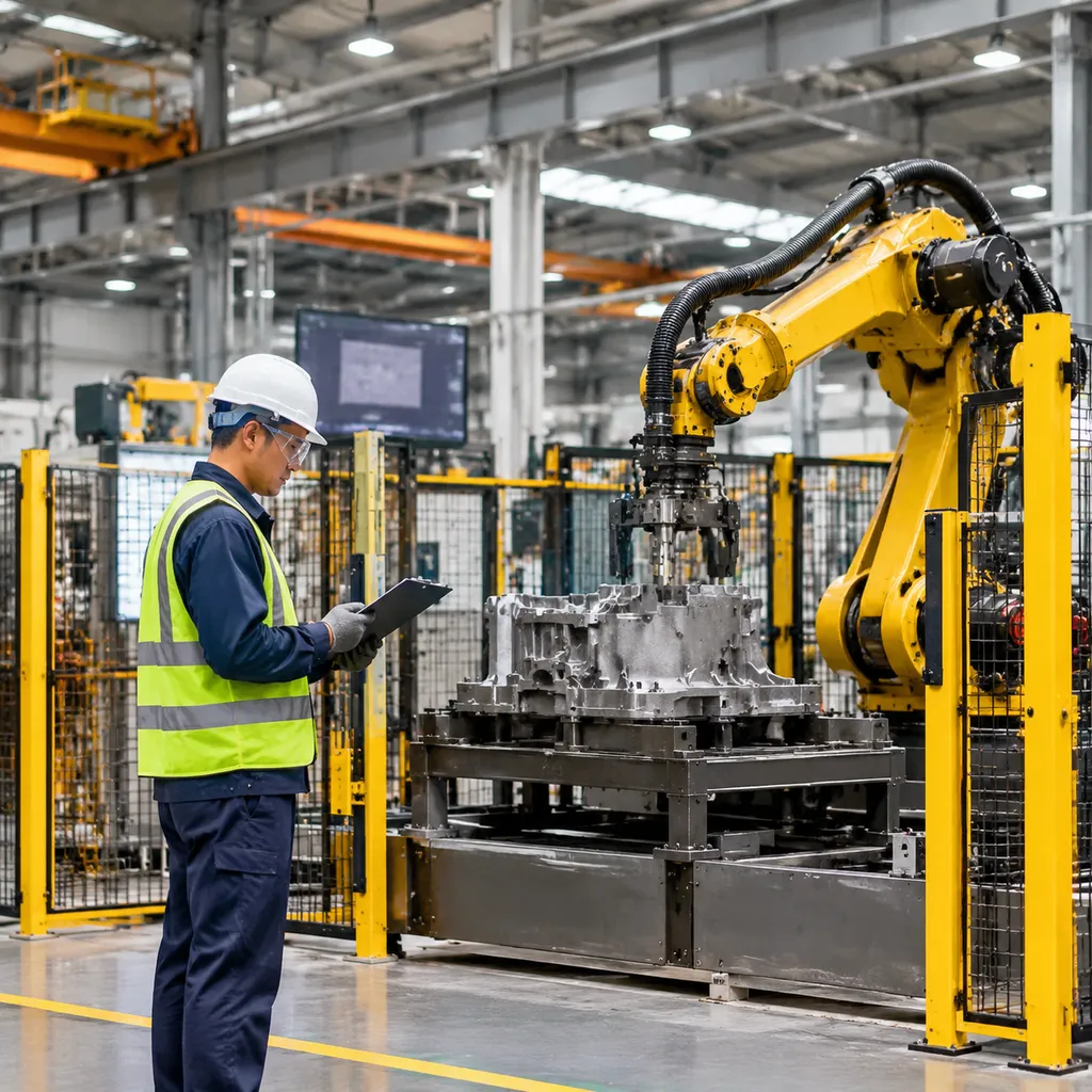
Foundry floors destroy standard industrial automation. Radiated heat from 700°C+ dies, airborne graphite dust, and molten metal splatter will degrade unhardened seals and cook internal electronics within weeks. When we specify and commission foundry automation robots for harsh environments, hardening the mechanical arm against thermal stress and particulate contamination is a non-negotiable step on the integration checklist.
Harsh-Environment Integration Checklist
- Specify Ingress Protection (IP67 or Foundry Grade): Never deploy an IP54 or IP65 robot near the pour or extraction zones. The minimum standard for arm and wrist axes is IP67, backed by two-part epoxy foundry coatings that shed molten metal and withstand high-pressure washdown chemicals.
- Deploy Thermal Protective Jackets and Viton Seals: For cycle extraction where wrist tools operate inches from hot tooling, fit high-silica aluminized heat jackets. Standard nitrile (NBR) seals fail under cyclic heat; replace them with Viton (FKM) fluorocarbon seals across all moving gearboxes and wrist joints to prevent oil degradation and seal breakdown.
- Armor Cabling and Pneumatics: Exposed rubber hoses melt instantly on contact with molten spatter. Route all pneumatic lines, servo cables, and sensor leads through fiberglass-silicone fire sleeves or flexible stainless steel armor. Where possible, route dress packs internally through the upper arm and wrist casting.
- Configure Positive Cavity Air Purge: Maintain a continuous positive pressure of 0.2 to 0.5 bar (3 to 7 psi) of dry, filtered air inside the robot arm cavities. This positive differential prevents micro-fine foundry dust, silica, and ambient moisture from migrating past dynamic seals into servo motors and harmonic reducers.
| Hardening Element | Standard Spec | Harsh Foundry Spec | Failure Risk Prevented |
|---|---|---|---|
| Environmental Ingress | IP54 / IP65 | IP67 (Foundry Plus standard) | Electrical shorts from mist & washdown |
| Joint Seals | NBR (Nitrile) | Viton / Fluorocarbon | Gearbox oil leaks from heat hardening |
| Internal Pressure | Atmospheric | Positive Dry Air Purge (0.3 bar) | Particulate entry into motors/encoders |
| Dress Pack Shielding | Polyurethane / PVC | Silicone-Coated Basalt/Fiberglass | Hose burn-through and signal loss |
End-of-Arm Tooling (EOAT) Design and Material Selection
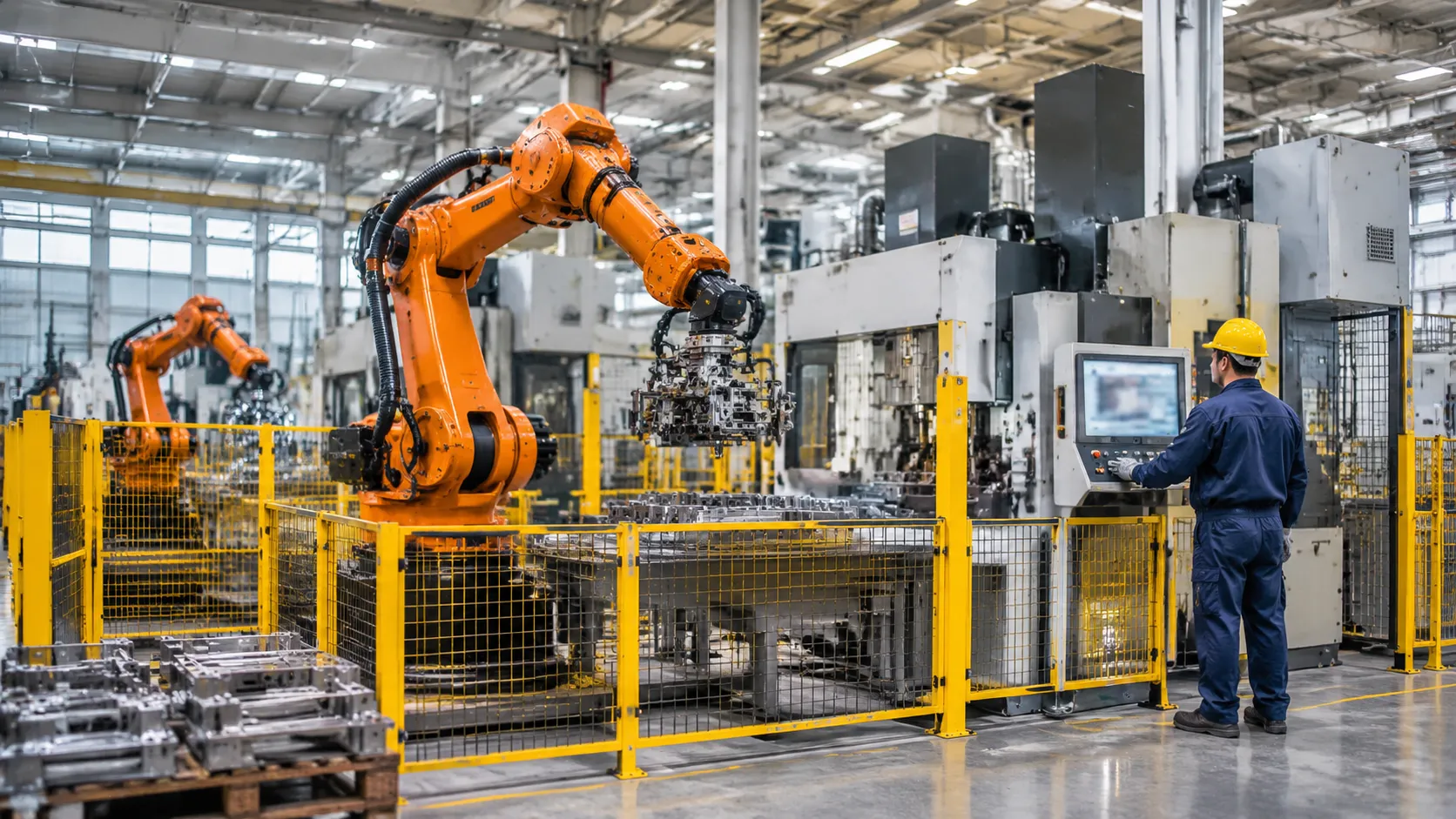
In any Foundry Robot Integration Checklist, the End-of-Arm Tooling (EOAT) is where theory meets raw physical punishment. We design foundry tooling to survive extreme radiant heat, abrasive parting lines, and relentless mechanical shock without dropping payload retention or cycle accuracy.
High-Temperature Gripper Materials and Ceramic Isolators
Standard aluminum gripper jaws fail quickly when handling parts fresh out of the mold. We isolate heat at the mechanical interface to protect the robot wrist sensors and internal wiring:
- Finger Construction: Mill gripper fingers from high-temperature alloy steels, beryllium copper, or hardened tool steels with EOAT heat shielding coatings.
- Ceramic Thermal Breaks: Mount machinable ceramic isolators (such as Macor or silicate ceramics) between the mechanical gripper body and the robot mounting flange. This stops thermal conduction dead in its tracks.
- Silicone and Viton Pads: For smooth extraction points, use high-temp fluoroelastomer contact pads rated to resist vulcanization and degradation under sustained contact above 300°C.
Pneumatic vs. Hydraulic Clamping for Heavy Sprues
Selecting the power source for your gripper depends entirely on part mass and gate geometry:
| Clamping Type | Operating Pressure | Best Use Case | Maintenance Factor |
|---|---|---|---|
| Pneumatic | 6 to 8 bar (shop air) | High-speed extraction, light-to-medium castings | Simple plumbing, zero risk of fluid fire near hot metal |
| Hydraulic | 70 to 140 bar | Massive iron sprues, heavy structural castings | Requires fire-resistant fluid (water-glycol), strict seal monitoring |
For high-volume production, pneumatic systems with mechanical toggle-lock linkages deliver fast cycles while mechanically locking onto the part, ensuring the casting stays secure even during sudden line pressure drops.
Quick-Change Tool Systems for Multiple Mold Variants
Foundry operations rarely run a single part number indefinitely. We incorporate heavy-duty robotic tool changers to swap grippers between product batches without human intervention:
- Hardened Alignment Pins: Tool changers must feature hardened steel locating pins to handle repeated blind dockings in dusty foundry environments.
- Sealed Utility Ports: Air, sensor signals, and cooling lines pass through sealed spring-loaded contacts and quick-exhaust blocks that block ambient sand and slag ingress.
- Variant Flexibility: Automated tool changers allow one cell to seamlessly shift between running components produced by investment and precision casting services for metal parts and larger structural molds.
Adding Compliance Mechanisms for Robotic Fettling and Grinding
During robotic fettling and grinding, casting tolerances fluctuate. Rigid tooling results in tool chatter, gouged parts, and premature spindle bearing failure.
- Radial and Axial Compliance: We integrate pneumatic deflection units that allow the cutting tool or grinding disc to float along casting contours, compensating for parting line variations.
- Constant Force Actuators: Active force-control heads maintain constant grinding pressure against the casting surface regardless of tool wear.
- Vibration Damping Mounts: Place elastomeric dampers between the compliance head and the robot arm to absorb high-frequency chatter before it vibrates the harmonic drives in the robot wrist.
Foundry Cell Safety and Industry Compliance
Integrating robots into a casting environment brings extreme thermal hazards, molten splatter, and heavy mechanical forces into direct contact with automation. Keeping human operators safe demands an uncompromising, layered defense system built straight into the cell architecture.
Meeting RIA R15.06 and ISO 10218 Safety Standards
We design every automated casting cell around RIA R15.06 and ISO 10218-1/-2 industrial robot safety mandates. Meeting these requirements requires a documented risk assessment that accounts for hot metal handling, rapid extraction, and de-gating forces:
- Risk Assessment Sign-Off: Identify crush zones, molten spray trajectories, and pinch points between the robot tooling and the casting machine platen.
- Safe Motion Control: Implement safety-rated soft axis and space limiting (SLS/PFL) inside the robot controller to keep the arm strictly contained within its physical envelope even during software anomalies.
- Mode Selection Lockouts: Ensure teach mode strictly enforces manual reduced speed (250 mm/s) with three-position enabling switches active on the teach pendant.
Positioning Safety Light Curtains, Area Scanners, and Interlocking Fences
Hard fencing and optical barriers must withstand the realities of the foundry floor, where airborne graphite, parting compound spray, and radiant heat easily trigger false trips on delicate sensors.
- Heavy-Duty Interlocking Fencing: We install welded wire mesh or solid steel lower perimeter guards at a minimum height of 2.0 meters, anchored directly into reinforced concrete. All service access doors feature Category 4 / PLe mechanical safety interlocks with guard locking to prevent entry until all cell inertia and high-heat cycles stop completely.
- Optoelectronic Sensors: Optical safety light curtains must be mounted well away from direct radiant heat zones, utilizing air-purged protective housings to keep dust from blinding the optical path.
- Laser Area Scanners: Set dual-zone laser safety scanners at load/unload staging zones to slow robot travel down to safe approach speeds before initiating a full protective stop if an operator breaches the perimeter.
| Safeguard Type | Minimum Rating | Typical Floor Location | Environmental Protection |
|---|---|---|---|
| Interlocked Perimeter Doors | Cat 4 / PLe, SIL 3 | Cell entry points, die maintenance gates | Heavy-duty key-trapped mechanical switches |
| Safety Light Curtains | Type 4 / SIL 3 | Pallet discharge & quench tank drop chutes | Air-purged IP67 glass housings |
| Laser Area Scanners | Type 3 / PLd | Part presentation tables & bin stands | Shielded base plates, vibration-damped |
| Blast Deflector Panels | Structural Steel | Die parting line line-of-sight | 3 mm to 5 mm solid steel plate |
Designing Emergency Stop Circuits and Category 4 Safety Relays
Standard control logic won't cut it when high-temperature melts are in motion. Safe integration relies on dedicated, dual-channel fail-safe hardware:
- Dual-Channel Cat 4 Architecture: Hardwire all E-stop buttons, gate switches, and perimeter interlocks through dual-channel safety relays or a certified safety PLC (F-CPU). A single component failure must never cause the loss of the safety function.
- Controlled Stop Integration (NFPA 79 Category 1): Program the primary safety sequence to perform a controlled decelerated stop rather than instantly dumping servo power. An abrupt dynamic stop while holding a ladle or fresh casting can violently eject molten metal across the cell. Servo brakes engage instantly once kinetic motion drops to zero.
- Emergency Stop Distribution: Position illuminated, palm-operated E-stop buttons at every operator station, teach gate, control console, and along conveyor exits.
Ensuring Blast Shields Protect Operators from Metal Splashes
A critical element of our foundry automation checklist is mitigating die spit and liquid metal splatter. During high-pressure die lockup, injection, or furnace tapping, pressurized liquid alloy can escape the tool parting line.
- Parting-Line Deflector Shields: Mount heavy-gauge steel deflector shields directly along the line of sight between the die split and any perimeter walkways or manual inspection benches.
- Clear Impact Viewing Panels: Where visual monitoring is critical—such as observing part extraction or ladle fill levels in a metal investment casting process cell—use high-impact polycarbonate view windows backed by replaceable tempered sacrificial glass sheets. The inner glass sheet absorbs molten burn marks and abrasive dust, leaving the structural polycarbonate panel structurally intact and crystal clear.
- Splash Containment Curtains: Hang fire-resistant silicone-coated fiberglass curtains around quench tanks and sprue-cutting hydraulic presses to trap flying flash and scalding steam.
Controls, Sensor, and PLC Handshake Integration
Robust electrical integration ties the robot directly into the foundry production rhythm. Without clean deterministic communication and foolproof handshaking, equipment collisions inside the die area become an expensive certainty.
Industrial Ethernet Communication Standards
Foundry floors generate intense electromagnetic interference from induction furnaces, large motors, and shot-end hydraulics. We avoid hardwired point-to-point I/O for cell control and standardize on industrial ethernet with shielded CAT6A or fiber runs:
- EtherNet/IP or Profinet: Run dedicated subnets with managed switches to isolate robot traffic from plant-wide networks.
- Update Times: Lock PLC-to-robot RPI (Requested Packet Interval) under 8ms to prevent cycle lag during high-speed extraction.
- Noise Immunity: Route signal cabling through grounded, rigid metal conduit separated by at least 12 inches from high-voltage furnace or motor feeds.
PLC Robot Handshake Protocol for Die Casting
A bulletproof handshake between the die casting machine (DCM) and the robot prevents closing the die on the tooling. We configure these signals across dedicated safety-rated registers:
| Signal Direction | Signal Name | Critical Function |
|---|---|---|
| DCM to Robot | Die Fully Open | Hardware interlock verifying mechanical stop before robot entry |
| DCM to Robot | Ejectors Forward | Confirms casting is pushed off the core pins for gripper access |
| Robot to DCM | Robot In Die Area | Freezes DCM hydraulic movement completely while tooling is inside |
| Robot to DCM | Part Extracted OK | Optical/vacuum confirmation verifying the cavity is clear |
| Robot to DCM | Robot Clear of Die | Drops safety gate bit to authorize die spray and closure |
3D Vision Systems for Raw Casting Handling
Foundry parts rarely sit in clean, predictable fixtures. Implementing custom automated systems with precision robotics and vision inspection allows us to pick unsorted castings straight from dross-heavy bins or cooling conveyors:
- Structured Light 3D Scanners: Handle changing ambient light and high surface reflectivity on freshly cast aluminum alloys.
- Point Cloud Matching: Identifies gate orientation, shifts in part geometry, and excessive flash before the gripper engages.
- Blow-Off Enclosures: Protect optical lenses with automatic pneumatic shutters and continuous positive air curtains to repel airborne mold release spray and graphite dust.
Force-Torque Sensors for Robotic Fettling and Grinding
Cast parting lines, gates, and risers vary from pour to pour. Rigid tool paths break cutting tools or gouge the final casting. We integrate 6-axis force-torque sensors on the robot wrist to handle dynamic material removal:
- Constant Force Maintenance: Regulates tool pressure (typically maintaining 15 to 40 N) against irregular gate stubs, preventing tool stalling or surface chatter.
- Automatic Wear Compensation: Real-time deflection feedback shifts robot coordinates as grinding wheels diminish in diameter.
- Defect Detection: Detects broken burrs or unformed sprues instantly by reading anomalous resistance during the deburring pass, flagging bad parts before downstream machining.
Foundry Robot Integration Checklist: Commissioning and Cold-Run Steps

Before we ever put a molten metal handling robot near an active furnace or die casting machine, we prove out every millimeter of movement cold. Rushing straight into live production is the fastest way to shear off a gripper or damage a dress pack. Here is the exact commissioning sequence we follow on the floor.
Offline Simulation and Collision Detection
- Verify 3D cell models: We import exact CAD files of the die, tie bars, quench tanks, and trim presses into our offline programming software before touching the teach pendant.
- Run full path sweeps: We test every approach and retract angle with the end-of-arm tooling (EOAT) fully modeled to catch interference points early.
- Check dress pack swing: We simulate hose and cable routing across extreme wrist rotations so thermal sleeves never pinch against the arm casting.
Software Limits, Safe Zones, and Home Positions
- Lock mechanical and software axis limits: We set strict joint boundaries so the arm physically cannot reach into operator walkways or smash into machine frames during a fault.
- Configure safety-rated zones: We program dual-channel safe zones that drop robot speed or trigger an immediate stop if a gate opens or a casting extraction robot cell drifts off path.
- Confirm true home recovery: We test the automatic return-to-home routine from multiple mid-cycle stop points so operators do not have to jog the arm out by hand after an E-stop.
Dry Cycles Without Molten Metal or Castings
We always start slow, then run the cell dry at full production speed for an extended shift block. Watch for mechanical drag and whip: At full acceleration, heavy EOATs and heat jackets reveal hose slap or loose mounting hardware that slow teach-mode runs hide. Test PLC handshakes: We simulate die-open, part-present, and clamp-release signals to confirm zero dead time between the robot and casting machine. Verify air and purge flow: We monitor positive air pressure inside the arm and thermal suits throughout continuous dry motion to ensure seals hold steady.
Live-Pour Cycle Times and Thermal Recovery
Once the cold run passes without a single fault, we transition to hot trials. Whether we are running high-volume production or rapid metal casting prototypes, heat changes how everything behaves. Benchmark takt time under load: We clock the live extraction, dipping, and transfer moves against our planned casting process steps to make sure the robot never bottlenecks the press. Monitor thermal recovery: We track servo motor temperatures and EOAT heat soak across consecutive pours to confirm the arm clears radiant heat zones quickly enough to cool down between cycles. Inspect post-run wear: After the first hot batch, we check gripper pads, ceramic isolators, and spatter shields for slag buildup or premature scorching.
| Commissioning Phase | Primary Focus | Shop-Floor Sign-Off Criteria |
|---|---|---|
| Offline Simulation | Reach & EOAT clearance | Zero collisions across all CAD envelopes |
| Zone & Limit Setup | Safe boundaries & homing | Clean auto-recovery from any mid-cycle fault |
| Cold Dry Run | Full-speed mechanics & PLC logic | Stable handshakes and zero hose snagging |
| Hot Live Trials | Takt time & heat management | Steady thermal baseline under continuous pours |
Preventive Maintenance and Wear Parts Strategy
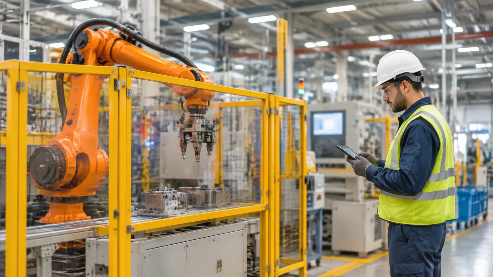
A solid foundry robot integration checklist does not end at startup. High ambient heat, abrasive airborne dust, and cyclic mechanical shock degrade components quickly. We keep our automated cells running without unplanned downtime by enforcing a strict maintenance schedule and keeping targeted replacement parts on the shop floor.
Critical Maintenance Cadence
| Component / Task | Inspection Frequency | Action Item |
|---|---|---|
| High-Heat Joint Grease | Every 500 operating hours | Sample for viscosity loss, particulate contamination, and thermal breakdown |
| Thermal Protective Jackets | Weekly visual check | Inspect for seam tears, molten splash burns, and zipper integrity |
| Wrist & Arm Seal Kits | Monthly inspection | Check Viton and pressurized seals for hardening or air leakage |
| Motor Torque Baselines | Continuous automated logging | Flag joint drag deviations exceeding ±8% from baseline |
High-Heat Joint Bearing Grease Analysis
Standard industrial robot lubricants break down fast near molten metals and preheat furnaces. We use synthetic, high-temperature fluorinated or polyurea-based greases rated for severe foundry environments. Pull grease samples from wrist axes (Axes 4, 5, and 6) every 500 to 1,000 hours. Look for dark discoloration, chemical separation, and metal fines. Purge bearings immediately if viscosity drops, preventing costly gearbox lockups during pours.
Critical Spares Inventory for Harsh Environments
To prevent an unexpected arm fault from halting an entire casting line—especially when unloading high-volume runs for a sand casting manufacturer—we stock ready-to-swap spares right at the cell: Pre-wired cable harnesses: Flexible, heat-resistant internal and external dressing cables. IP67 replacement seal kits: High-temp Viton gaskets and positive-pressure regulator valves. Custom gripper fingers: Hardened steel or ceramic-coated contact pads to maintain grip on hot sprues. Thermal jacket panels: Spare modular sleeves to swap out scorched sections without replacing the whole suit.
Routine Thermal Jacket Inspections
A torn protective suit exposes the robot arm to direct radiant heat and abrasive foundry sand. We check high-flex areas around the wrist and elbow joints at every shift turnover. Clear away accumulated slag, metal splatter, and binder dust that can wear through outer fiberglass or Kevlar layers. Verify positive purge air pressure inside the suit to guarantee that hot dust stays out.
Tracking Motor Torque to Catch Early Mechanical Drag
Mechanical wear reveals itself in motor telemetry long before an axis fails. We record baseline motor torque signatures during dry cycles at commissioning. Review automated torque trends across all six axes weekly. Rising torque values on specific joints signal bearing wear, dried grease, or misalignment. Catching mechanical drag early protects downstream tolerances, ensuring consistent extraction and positioning before parts move to secondary precision machining component operations.
Foundry Robot Integration FAQs
Addressing edge cases early keeps the floor running smoothly. Here are the most frequent operational issues we solve when engineering a turnkey Foundry Robot Integration Checklist:
How do I protect robot wrists from molten aluminum splatter?
Direct splatter degrades seals and bakes cabling instantly. We protect robot wrists using multi-layered defense: Thermal Sleeves & Jackets: Kevlar or aluminized fiberglass jackets with silicone outer coats shield against heat radiation and shed molten aluminum drips. Positive Air Purging: Supplying continuous, low-pressure filtered instrument air into the robot wrist cavity stops airborne metallic dust and ambient heat from pulling into internal gears. Mechanical Deflectors: Heavy-gauge stainless steel blast shields installed directly behind the end-of-arm tooling intercept splash paths during high-pressure die opening.
What is the typical cycle-time reduction when automating casting extraction?
On average, our foundry casting robotics integration cells deliver a 15% to 30% reduction in total cycle time compared to manual extraction.
Beyond raw seconds saved, the major gain is steady-state pacing. A die casting robot arm operates without heat fatigue, entering the open mold within milliseconds of die separation, executing consistent spray and extract cycles, and moving hot parts immediately into quench baths without variable cool-off delays.
Can standard industrial robots handle heavy fettling and grinding vibration?
No. Standard industrial robots experience rapid gear wear, encoder faults, and arm backlash when subjected to rough degating, grinding, and fettling forces.
For rough de-flashing and grinding, we deploy heavy-duty foundry grade robotic arm models equipped with: Heavy-duty cast construction with IP67 protection across all joints. High-torque RV reduction gears capable of soaking up continuous deflection. Active force-compliance systems that modulate tool pressure dynamically, absorbing impact before structural chatter damages internal bearings.
How do we manage robot downtime during unexpected die cast machine faults?
We configure robust PLC robot handshake protocols to ensure clean cell recovery during unexpected interlock breaks, short shots, or machine e-stops: Safe-Zone Logic: If the die cast machine faults mid-stroke, the robot controller freezes motion or retracts along an established interference-free vector into an idle wait station. Part-In-Gripper Validation: Optical sensors and pneumatic pressure switches instantly confirm part status. If an extraction fails, the robot halts to prevent the die from closing on stuck castings. One-Touch Cycle Clearing: Cell HMI panels feature dedicated recovery routines allowing floor technicians to jog arms safely to maintenance perches without zero-loss re-homing.


 English
 Russian
 German