
2026年9月29日
Explore the casting process from mold design to finished parts for quality precision and efficient production
Core Principles of the Metal Casting Process
Metal casting is a primary manufacturing process where we pour molten metal into a heat-resistant mold cavity replicating the target geometry. As the liquid metal cools, it solidifies into a near-net-shape part, ready for shakeout, machining, or heat treatment. This working mechanism allows us to manufacture complex geometries, internal passageways, and massive structural components that are cost-prohibitive or impossible to produce via subtractive machining or fabrication alone.
Molten Alloy Preparation ➔ Cavity Filling via Gating ➔ Controlled Phase Solidification ➔ Net-Shape Component
Key Elements of the Casting System
A functional casting setup relies on five synchronized elements designed to handle extreme thermal loads and maintain tight dimensional accuracy:
- Pattern: The physical replica of the exterior part geometry, scaled up to account for alloy-specific thermal contraction and machining allowances.
- Mold: The outer forming shell (made of bonded sand, ceramic, or high-grade tool steel) that contains the negative shape of the final component.
- Core: Refractory inserts placed inside the mold cavity to generate hollow sections, internal fluid passages, and intricate undercuts.
- Gating System: The channel network—consisting of a pouring basin, downsprue, runner, and ingates—engineered to deliver molten metal into the cavity smoothly with zero turbulence.
- Riser (Feeder): A dedicated reservoir of liquid metal that stays molten longer than the casting body, feeding liquid volume back into the part to neutralize solidification shrinkage.
| Casting Element | Primary Function | Failure Risk if Miscalculated |
|---|---|---|
| Pattern & Core | Defines outer and inner part geometry | Dimensional deviation, improper wall thickness |
| Gating System | Controls metal velocity and flow balance | Slag inclusion, air entrapment, mold erosion |
| Riser (Feeder) | Supplies supplemental liquid during freezing | Internal shrinkage cavities, micro-porosity |
Thermodynamic Phase Change and Solidification
Transforming liquid alloy into an engineering-grade solid component involves three distinct thermodynamic stages:
- Superheat Dissipation: The molten metal loses sensible heat as it flows into the mold until it hits its liquidus temperature. Gating design must ensure the mold fills completely before freezing begins.
- Latent Heat of Fusion & Solidification: The alloy transitions through a "mushy zone" between liquidus and solidus temperatures. Solidification begins at the mold walls with rapid, fine-grain nucleation (chill zone) and grows inward toward the thermal center as columnar or equiaxed dendrites.
- Solid-State Contraction: Once fully solidified, the metal continues to cool to ambient temperature, undergoing linear dimensional shrinkage. We calculate exact pattern shrink rates to keep final dimensions strictly within blueprint tolerances.
Step-by-Step Metal Casting Process Workflow
Transforming raw ingots into high-integrity components requires strict thermal and mechanical discipline at every stage. In our foundry operations, we break the complete metal casting process down into seven distinct, repeatable steps to guarantee dimensional accuracy and structural integrity.
+-----------------------------------------------------------------------------------+ | THE 7-STEP CASTING WORKFLOW | | | | [1. Pattern & Cores] --> [2. Mold Prep] --> [3. Melt & Treatment] | | | | | | | v v v | | [4. Pouring Flow] --> [5. Solidification] --> [6. Shakeout & Fettling] | | | | | v | | [7. Heat Treat & Finish] | +-----------------------------------------------------------------------------------+
Step 1: Patternmaking and Core Production
Every casting begins with geometry definition. We create a pattern—an exact physical replica of the exterior part with shrinkage allowances added:
- Pattern tooling: Machined from wood, aluminum, steel, or polyurethane resin depending on volume requirements.
- Core manufacturing: Sand mixed with chemical binders is blown into core boxes to form internal passages and hollow channels.
- Rapid tooling alternative: For prototypes or complex geometries, we eliminate hard tooling by utilizing a 3D printed sand mold for rapid patternless precision casting to cut lead times from weeks to days.
Step 2: Mold Preparation and Assembly
The mold forms the negative cavity that receives liquid metal:
- Sand systems: We pack green sand or chemically bonded resin sand around the pattern in two halves—the cope (top) and drag (bottom).
- Gating integration: We carve or mold the sprue, runners, ingates, and risers to guide metal cleanly into the cavity.
- Core setting & closing: Cores are set into core prints within the drag, vents are cleared to release gases, and both halves are clamped tightly to prevent parting line blowout.
Step 3: Metal Melting and Chemical Melt Treatment
Molten metal quality dictates mechanical properties before pouring even starts:
- Melting: Base charge and master alloys are melted in medium-frequency induction furnaces or electric arc furnaces.
- Degassing & fluxing: We inject inert gases (such as argon or nitrogen) and fluxes to remove dissolved hydrogen and trap non-metallic inclusions.
- Melt inoculation & chemistry check: We use optical emission spectrometry (OES) to verify elemental composition, adding inoculants (like ferrosilicon or magnesium for ductile iron) right before tapping.
Step 4: Pouring and Mold Filling Dynamics
Pouring is where fluid dynamics meet thermal control:
- Temperature control: We maintain a strict pouring temperature window. Pouring too cold leads to misruns and cold shuts; pouring too hot causes gas absorption and mold erosion.
- Laminar filling: We design gating ratios to ensure smooth, non-turbulent flow, preventing molten metal oxidation and air entrapment during mold fill.
Step 5: Cooling, Solidification, and Feeding Mechanisms
As the molten alloy transitions from liquid to solid, volume reduction occurs:
- Directional solidification: We design the thermal gradient so cooling moves progressively from the thinnest sections toward the heaviest walls.
- Riser feeding: Insulated or exothermic risers act as molten reservoirs, feeding liquid metal into heavy sections to compensate for solidification shrinkage and prevent internal voids.
Step 6: Shakeout, Knockout, and Fettling
Once the part cools below its critical transformation temperature, we extract the raw casting:
- Shakeout & knockout: Vibratory tables or knockout drums fracture the sand mold, freeing the cast component and dislodging internal cores.
- Fettling & degating: Cut-off saws, plasma torches, or hydraulic wedges remove the gating and riser system.
- Surface cleaning: Parts undergo shot blasting with steel grit to remove scale, residual sand, and flash.
Step 7: Post-Casting Heat Treatment and Surface Finishing
The final step stabilizes microstructure and prepares the part for final application:
| Operation | Primary Purpose | Common Methods |
|---|---|---|
| Heat Treatment | Relieves internal stress, increases hardness, or improves ductility | Annealing, Normalizing, Quench & Temper, T6 Solutionizing |
| Machining | Hits tight tolerances on critical sealing faces and bore diameters | CNC milling, turning, and boring to drawing specifications |
| Surface Finishing | Corrosion protection and cosmetic appeal | E-coating, powder coating, zinc plating, or passivation |
For applications requiring net-shape accuracy with minimal final machining, reviewing our guide on metal investment casting process tolerances and materials helps determine whether precision investment methods or standard sand tooling best fit your component requirements.
Major Types of Casting Processes and Selection Criteria
Choosing the right metal casting process comes down to production volume, part complexity, dimensional tolerance, and tooling budget. Here is how we break down the primary industrial casting technologies and where each delivers the highest ROI.
Sand Casting: Versatile and Cost-Effective
Sand casting remains the most adaptable method for low-to-medium production runs and oversized components across all alloy types.
- Green Sand Molding: Uses a moist mix of silica sand, bentonite clay, and water. It is fast, economical, and ideal for high-volume iron and bronze castings. We frequently weigh the benefits of the green sand casting process against higher-precision tooling when starting early production runs.
- Resin Sand (No-Bake): Binds sand grains with chemical resins that cure at room temperature. It delivers far better surface finishes and dimensional stability than green sand for large pump housings and engine frames.
- Air-Set Sand: Uses organic binders that harden upon air exposure, providing uniform mold rigidity for heavy, intricate industrial components.
Die Casting: High-Speed Production for Non-Ferrous Alloys
Die casting forces molten metal under pressure into reusable steel dies, making it the premier choice for thin-walled, high-volume parts.
- High-Pressure Die Casting (HPDC): Injects molten aluminum, zinc, or magnesium at pressures up to 1,500 bar. Cycle times are extremely fast (seconds per shot), producing near-net-shape components with minimal post-machining.
- Low-Pressure Die Casting (LPDC): Moves metal upward into the die under low pressure (0.2–1 bar). This produces laminar, turbulence-free filling with minimal oxide inclusion—standard for structural automotive wheels and safety-critical brackets.
Investment Casting: Maximum Precision and Surface Finish
Also known as the lost-wax method, investment casting builds a refractory ceramic shell around an expendable wax pattern.
- Ceramic Shell Precision Casting: Capable of holding tight tolerances (±0.005 in/in) and Ra 3.2 µm surface finishes on difficult-to-machine superalloys, stainless steels, and titanium.
- Complex Geometry Without Parting Lines: Allows for undercuts, thin walls, and fine lettering. Comparing lost-wax casting vs sand casting is our standard approach when evaluating whether lower machining costs justify investment casting tooling.
Centrifugal Casting: High-Integrity Cylindrical Parts
Centrifugal casting pours molten metal into a rapidly spinning die (300 to 3,000 RPM). Centrifugal force throws the dense liquid against the outer walls while lighter impurities, oxides, and gases float to the inner diameter for easy boring.
- True Centrifugal: Spins along a horizontal or vertical axis without a central core; ideal for pipes, cylinder liners, and gun barrels.
- Semi-Centrifugal: Uses a core to shape internal geometry, typically used for symmetric parts like gear blanks, wheels, and pulleys.
- Centrifuging: Arranges multiple individual molds around a central sprue to force metal into intricate details through rotational pressure.
Permanent Mold Casting: Gravity-Fed Durability
Permanent mold casting relies on gravity to feed molten metal into pre-heated iron or steel dies.
- Best for Non-Ferrous Parts: Primarily handles aluminum, magnesium, and copper alloys.
- Superior Mechanical Properties: Faster cooling rates in metal molds yield a much finer grain structure and higher tensile strength than sand casting, making it ideal for automotive pistons, connecting rods, and marine hardware.
Lost Foam Casting: Evaporative Pattern Technology
Lost foam uses an expanded polystyrene (EPS) pattern coated in a refractory slurry and packed into unbonded dry sand.
- No Cores or Draft Required: As the molten metal is poured, it instantly vaporizes the foam pattern, taking its exact shape.
- One-Piece Complex Assemblies: Eliminates internal cores, parting lines, and draft angles, allowing multiple sub-assemblies (such as engine cylinder heads with integrated intake manifolds) to cast as a single solid unit.
Continuous Casting: High-Throughput Mill Stock
Continuous casting converts molten metal directly into standardized semi-finished profiles without individual molds.
- Process: Molten metal flows through a water-cooled copper mold, partially solidifying a solid skin before rollers draw it downward through spray zones.
- Output: Continuous production of billets, slabs, and blooms for structural steel, wire drawing, and forging stock with minimal end-crop scrap.
Process Selection Matrix
| Casting Method | Typical Tolerance | Surface Roughness ($R_a$) | Tooling Cost | Minimum Economic Run |
|---|---|---|---|---|
| Green Sand | ± 0.5 - 1.5 mm | 12.5 - 25\ μm | Low | 1 - 50 pcs |
| Investment (Lost Wax) | ± 0.1 - 0.3 mm | 1.6 - 3.2\ μm | Medium - High | 100 - 1,000 pcs |
| HPDC Die Casting | ± 0.05 - 0.2 mm | 0.8 - 1.6\ μm | High | 5,000+ pcs |
| Permanent Mold | ± 0.3 - 0.8 mm | 3.2 - 6.3\ μm | Medium | 500 - 2,000 pcs |
| Lost Foam | ± 0.2 - 0.5 mm | 3.2 - 6.3\ μm | Medium - High | 1,000+ pcs |
| Centrifugal | ± 0.4 - 1.0 mm | 3.2 - 12.5\ μm | Medium | 50 - 500 pcs |
Common Materials and Alloys in the Casting Process
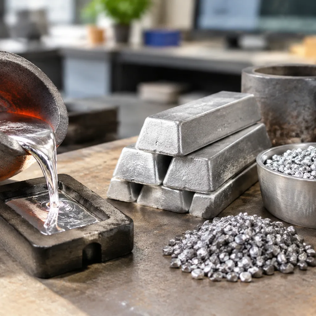
Choosing the right alloy determines how well molten metal fills the mold cavity, solidifies without defects, and performs under mechanical stress. We categorize casting alloys into ferrous and non-ferrous groups based on base chemistry, melting characteristics, and target application requirements.
Ferrous Casting Metals
Ferrous alloys deliver the structural rigidity, wear resistance, and load-bearing capacity needed for heavy industrial components.
- Gray Iron: Characterized by its flake graphite microstructure, gray iron offers exceptional vibration damping, high compressive strength, and effortless machinability. We rely on it heavily for machine tool beds, engine blocks, and brake rotors.
- Ductile Iron: Treated with magnesium to form nodular graphite, ductile iron casting matches carbon steel in tensile strength and yield performance while retaining superior castability and impact resistance.
- Carbon Steel: Offers high toughness, ductility, and weldability for structural components. It has a higher melting point and greater solidification shrinkage than cast iron, demanding robust gating and feeding designs.
- Alloy Steel: Formulated with elements like chromium, nickel, and molybdenum to withstand severe mechanical wear, corrosive environments, and elevated operating temperatures.
Non-Ferrous Casting Metals
Non-ferrous alloys provide weight savings, electrical conductivity, and natural corrosion resistance across precision applications.
- Aluminum Alloys: Combine a low melting point with high strength-to-weight ratios and excellent thermal conductivity. Review our aluminum alloy casting guide to select the right grade (such as A356 or A380) for sand, permanent mold, or die casting processes.
- Zinc Alloys: Exhibit high fluidity and low melting temperatures, making them the standard choice for ultra-thin, high-precision die-cast parts with smooth surface finishes.
- Magnesium Alloys: The lightest structural metals available, ideal for lightweight automotive powertrain brackets, power tools, and aerospace housings.
- Copper and Bronze Alloys: Offer outstanding thermal and electrical conductivity, low friction coefficients, and superior resistance to saltwater corrosion in marine hardware, pump impellers, and sleeve bearings.
Key Material Selection Factors
When evaluating an alloy for a component, we balance four core metallurgical and foundry variables:
| Selection Parameter | Foundry & Process Impact | Engineering Consideration |
|---|---|---|
| Fluidity | Dictates how easily molten metal fills thin sections and intricate details before freezing. | High-silicon aluminum and gray iron fill complex geometries easily; low-carbon steels require higher superheat. |
| Shrinkage Rate | Volumetric contraction during liquid-to-solid phase change. | Dictates pattern scaling and riser placement to prevent shrinkage cavities and hot tearing. |
| Melting Point | Determines mold material limits, furnace energy demands, and cycle times. | Low-temp alloys utilize permanent steel tooling; high-temp alloys require refractory sand or ceramic shells. |
| Mechanical Properties | Defines tensile strength, yield, elongation, hardness, and fatigue limits. | Determines whether post-casting heat treatment (e.g., annealing, quenching, T6 aging) is required to meet spec. |
For detailed mechanical data and alloy grade comparisons, check our casting alloy properties and material selection guide.
Design for Manufacturability (DFM) in Casting
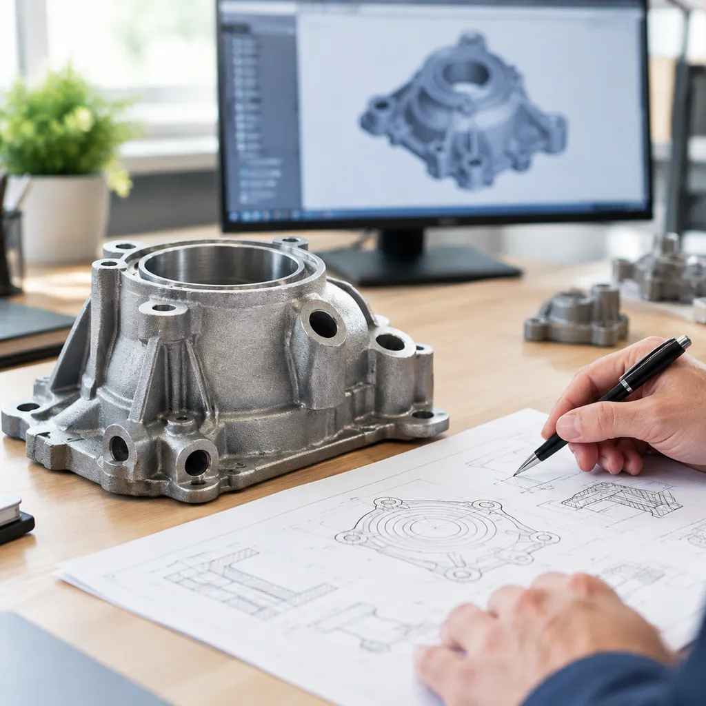
Smart casting design prevents defects before molten metal ever touches the mold. When we evaluate component geometry for any casting process, our goal is simple: maximize moldability, maintain structural integrity, and eliminate unnecessary secondary machining costs.
Draft Angles and Parting Line Placement
Every rigid mold pattern requires draft angles to allow clean part ejection without damaging the mold cavity walls.
- Parting Line Optimization: We always place the parting line along a single flat plane whenever possible. This prevents mold mismatch, simplifies tooling design, and keeps flash to a minimum.
- External Draft Angles: A standard draft of 1° to 2° works for most sand and permanent mold tooling.
- Internal Features: Deep pockets and cores require 2° to 5° of draft to counteract shrinkage grip as the cooling metal contracts around the mold material.
Uniform Wall Thickness and Rib Design
Non-uniform cross-sections lead directly to thermal imbalance, sink marks, and internal shrinkage porosity.
- Maintain Uniform Walls: Keep wall thickness as consistent as possible throughout the part to ensure a balanced, progressive solidification front.
- Tapered Transitions: When wall thickness changes are unavoidable, we design a gradual taper with a minimum 3:1 length-to-thickness ratio rather than a sharp step.
- Structural Rib Rules: Use reinforcing ribs instead of thick walls to add rigidity. Design rib thickness between 40% and 60% of the nominal base wall thickness to prevent sink marks on the cosmetic face.
| Feature | Best Practice Rule | Primary Defect Avoided |
|---|---|---|
| Nominal Wall | Consistent across the entire geometry | Hot spots and localized shrinkage |
| Wall Transitions | 3:1 gradual blending slope | Hot tears and thermal stress cracking |
| Rib Thickness | 0.4 to 0.6 × Nominal Wall | Surface sink marks and porosity |
| Internal Fillets | Radius = Nominal Wall Thickness | Stress concentration and turbulence |
Fillets, Radii, and Stress Reduction
Sharp corners disrupt metal flow, cause turbulent mold filling, and act as high-stress focal points during cooling.
- Internal Fillets: We radius all inside corners to match the nominal wall thickness ($R \approx T$). This promotes laminar metal flow and eliminates stress risers.
- External Radii: Outside corners should use a radius of roughly 1.5 × T to prevent edge chilling, cold shuts, and premature tool chipping during post-process machining.
Machining Allowances and Dimensional Tolerances
Over-specifying dimensional precision drives tooling costs through the roof. We design castings with targeted machining stock only where critical functional surfaces demand tight fits.
- Machining Stock Allowances: We typically add 1.5 mm to 3.0 mm of extra material on sand-cast surfaces that require post-machining. For precision methods like aluminum investment casting tight tolerances, we can reduce this allowance below 0.8 mm or eliminate secondary milling entirely.
- Datum Positioning: Place primary datum targets on stable, un-machined cast features located away from the parting line and gating cutoff points to maintain consistent CNC fixturing.
Casting Defects, Root Causes, and Quality Control

In any casting process, catching defects early prevents costly scrap and field failures. We focus on pinpointing root causes during molten metal pouring and solidification to apply immediate, reliable casting defects and remedies.
Gas Porosity, Pinholes, and Blowholes
Gas entrapment is one of the most common issues in foundry work. It creates internal or surface voids that weaken mechanical strength.
- Pinholes: Tiny subsurface gas bubbles caused by hydrogen absorption in the melt or moisture in the mold.
- Blowholes: Larger, smooth-walled internal cavities caused by trapped air or steam that fails to escape through mold vents.
- Remedies: Degas the melt with inert gas purging (like nitrogen or argon), preheat ladles, bake sand cores thoroughly, and increase mold permeability with proper venting channels.
Shrinkage Cavities and Sink Marks
Metals shrink as they cool from liquid to solid. When the volume reduction is not compensated with fresh liquid metal, shrinkage defects occur.
- Macroporosity and Cavities: Jagged, irregular voids that form in the last-to-freeze thermal centers of heavy sections.
- Sink Marks: Surface depressions that form when outer walls pull inward toward a contracting thick section beneath.
- Remedies: Redesign the gating and riser system to promote directional solidification toward feed reservoirs. Add internal or external chills to accelerate cooling at thick junctions, or review our die casting vs sand casting guide to pick a process tailored to your section thickness requirements.
Cold Shuts, Misruns, and Flow Lines
These defects stem from premature metal cooling or poor fluid flow inside the mold cavity.
- Misrun: The liquid metal solidifies before completely filling the mold cavity, leaving an incomplete part.
- Cold Shut: Two converging streams of molten metal meet but fail to fuse seamlessly, leaving a visible seam or weak plane.
- Remedies: Increase pouring temperature, raise mold preheat temperatures, widen narrow gate runners, and optimize pouring speed to prevent flow turbulence.
Hot Tears, Cracking, and Residual Stress
Hot tears occur when thermal contraction is mechanically restrained while the alloy is in a semi-solid, mushy state.
- Root Causes: Mold or core rigidity that resists alloy contraction, sharp internal corners causing stress concentrations, and uneven cooling rates across variable wall thicknesses.
- Remedies: Use core binders with high collapsibility, increase fillet radii at all section intersections, balance wall transitions, and apply post-casting stress-relief annealing.
Non-Destructive Testing (NDT) for Castings
We verify structural integrity and internal soundess through standard non-destructive testing casting protocols:
| NDT Inspection Method | Defect Detection Capability | Typical Application |
|---|---|---|
| Radiographic Testing (X-Ray / CT) | Internal shrinkage cavities, gas porosity, inclusions, and core shifts | High-integrity aerospace brackets, engine components, and pressure valves |
| Ultrasonic Testing (UT) | Deep internal cracks, laminar flaws, and wall thickness variations | Heavy iron castings, large steel forgings, and thick-section housings |
| Dye Penetrant Inspection (PT) | Surface-breaking cracks, cold shuts, pinholes, and micro-porosity | Non-ferrous aluminum, zinc, and stainless precision castings |
| Magnetic Particle Inspection (MT) | Surface and immediate subsurface cracks and seams | Ferrous ductile iron, gray iron, and carbon steel components |
Industrial Applications of the Casting Process
We rely on the modern casting process to produce complex, near-net-shape metal parts where high-volume production, intricate internal channels, or heavy section thicknesses make subtractive machining impractical. Below are the key industrial sectors and their primary cast components.
Automotive Sector
The automotive industry depends heavily on automated casting lines to balance light weighting, structural rigidity, and low unit costs.
- Engine Blocks: Poured using gray iron or aluminum alloys to maintain dimensional stability, dampen engine vibrations, and withstand continuous thermal cycling.
- Cylinder Heads: Cast with intricate sand cores to form high-precision coolant jackets and internal intake/exhaust ports.
- Transmission Cases: Produced predominantly via high-pressure die casting to achieve thin-walled, high-strength aluminum enclosures that reduce curb weight while sealing high-pressure fluids.
Aerospace Industry
Aerospace demands zero-defect metallurgical integrity, thin walls, and high strength-to-weight ratios under severe operating conditions.
- Turbine Blades: Manufactured using vacuum investment casting (directional solidification or single-crystal growth) to resist creep and extreme thermal fatigue in jet engine hot sections.
- Structural Brackets & Airframe Nodes: Cast using aerospace-spec alloys like high-strength aluminum grade 357 to deliver high yield strength, excellent fracture toughness, and tight dimensional control.
- Fuel & Hydraulic Pump Housings: Investment-cast to form complex internal fluid channels with smooth internal surface finishes and guaranteed pressure containment.
Heavy Machinery & Equipment
For severe-duty industrial hardware, casting delivers the bulk mass, mechanical damping, and wear resistance required for continuous operation.
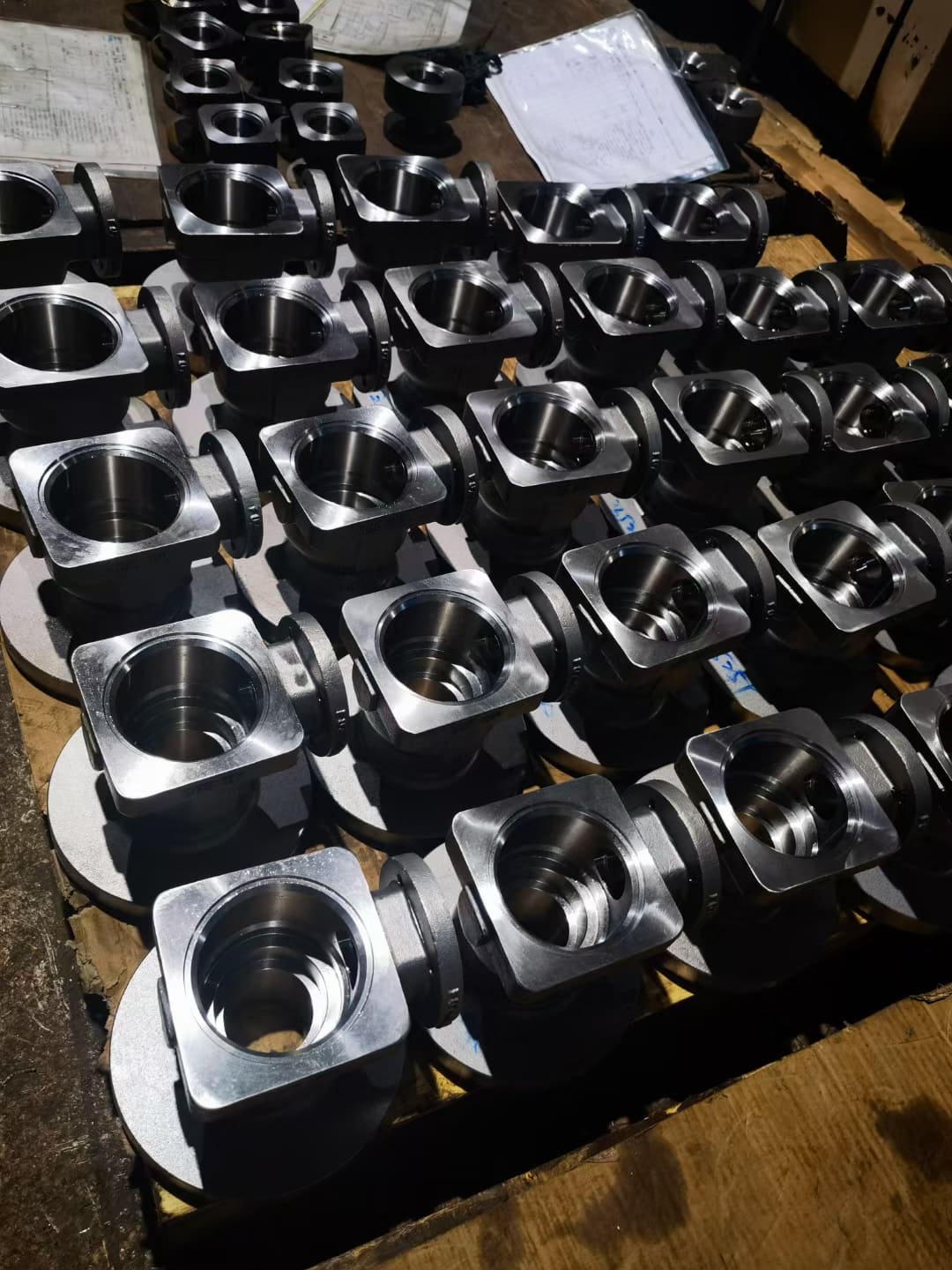
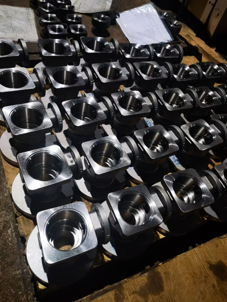
- Valve Bodies: Cast from ductile iron, carbon steel, or stainless steel to manage high-pressure, abrasive, and corrosive flow media without wall porosity.
- Pump Impellers: Cast with curved, balanced internal vanes to optimize fluid dynamics and resist cavitation erosion in high-flow pumping systems.
- Hydraulic Manifolds: Produced in ductile iron to integrate multi-axis fluid circuits into a single leak-free block, eliminating external plumbing lines.
- Wear Plates & Chutes: Poured with high-chromium white irons and manganese steels to endure severe impact and abrasion, frequently maintained or surfaced with cobalt welding alloys for high wear and heat resistance.
Industry Application Summary
| Sector | Core Cast Components | Primary Materials | Key Manufacturing Driver |
|---|---|---|---|
| Automotive | Engine blocks, transmission housings, suspension knuckles | A380 Aluminum, Ductile Iron, Gray Iron | High volume, low cycle times, mass reduction |
| Aerospace | Turbine blades, structural brackets, fuel manifolds | Ti-6Al-4V, IN718, Al 357, A356 | High strength-to-weight, zero internal porosity |
| Heavy Machinery | Valve bodies, pump impellers, wear plates, crusher jaws | WCB Carbon Steel, High-Cr Iron, Ductile Iron | High mechanical strength, wear & fatigue resistance |
Cost Factors and Selection Matrix for Casting Methods
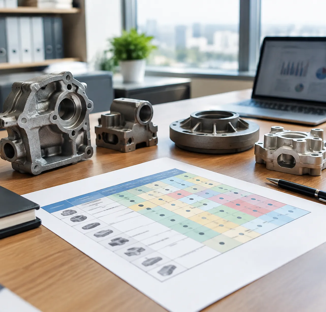
Choosing the right casting process comes down to balancing initial tooling capital against long-term part production runs. When we evaluate component manufacturing costs, we look at tooling amortization, volume scalability, and how as-cast tolerances eliminate costly secondary operations.
Tooling Costs vs. Unit Price Economics
Every method trades upfront tooling investment for per-unit cycle time and piece price:
- Sand Casting: Minimal upfront tooling cost (wood or resin patterns), but higher labor and unit costs make it ideal for low-to-medium runs.
- Investment Casting: Moderate tooling investment (aluminum wax injection dies) with near-net-shape output that minimizes finish machining.
- High-Pressure Die Casting (HPDC): High initial tooling expenditure (hardened tool steel dies), delivering the lowest unit cost for massive production runs.
- Permanent Mold Casting: Moderate-to-high mold expense with lower per-piece cycle costs than sand methods.
| Casting Method | Tooling Initial Cost | Unit Piece Price | Economic Run (Volume) | As-Cast Tolerance | Surface Roughness ($Ra$) | Secondary Machining Needed |
|---|---|---|---|---|---|---|
| Green Sand | Low | Moderate - High | 1 – 1,000 | ± 0.030" - 0.060" | 250 - 500\ μin | High |
| Resin / Air-Set Sand | Low - Moderate | Moderate | 10 – 5,000 | ± 0.015" - 0.030" | 150 - 300\ μin | Moderate |
| Investment Casting | Moderate | Moderate | 100 – 50,000+ | ± 0.005" - 0.010" | 63 - 125\ μin | Minimal |
| Permanent Mold | Moderate - High | Low - Moderate | 1,000 – 20,000+ | ± 0.010" - 0.020" | 100 - 200\ μin | Low - Moderate |
| High-Pressure Die | High | Lowest | 10,000 – 100,000+ | ± 0.002" - 0.005" | 32 - 63\ μin | Minimal |
Volume Thresholds and Batch Economics
Batch size strictly dictates the most viable casting technology:
- Prototypes & Short Runs (1 to 100 units): Sand casting or 3D-printed sand molds eliminate hard tooling risks. We frequently deploy precision investment casting and prototypes when testing complex geometries before cutting dedicated tooling.
- Mid-Scale Production (500 to 5,000 units): Resin sand and ceramic shell investment methods keep pattern amortization manageable without sacrificing dimensional repeatability.
- High-Volume Mass Production (10,000+ units): Automated die casting absorbs high tool steel costs across hundreds of thousands of cycles, dropping unit prices to baseline material and press-time rates.
Surface Finish, Tolerances, and Post-Machining Trade-Offs
Raw casting costs represent only a portion of the total landed cost. Rough casting methods shift the financial burden downstream to CNC finishing cells:
- Tight As-Cast Geometries: Investment casting and die casting hit critical tolerances right out of the mold, eliminating face-milling, contouring, and deep-hole drilling.
- Rough Surface Allowances: Sand castings demand heavy machining allowances ($0.120" - 0.250"$), driving up spindle wear, cycle times, and scrap generation.
- Total Cost Optimization: Balancing mold costs against integrated precision casting and CNC machining provides the most cost-effective path to finished, print-ready components.
Frequently Asked Questions About the Casting Process
What is the primary difference between casting and forging?
The core difference lies in the state of the material during shaping. In the metal casting process, we melt the alloy completely into a liquid state and pour it into a mold cavity. This allows us to produce intricate internal geometries, hollow sections, and complex shapes with minimal machining.
Forging deforms solid metal under extreme compressive pressure using dies, aligning the internal grain structure along the part profile.
| Parameter | Metal Casting | Metal Forging |
|---|---|---|
| Material State | Fully molten liquid metal | Solid heated billet/ingot |
| Geometric Complexity | High (internal cores, undercuts) | Moderate to low |
| Tooling Startup Cost | Low to moderate | High |
| Structural Grain | Isotropic, non-directional | Directional grain flow |
| Best For | Complex housings, engine blocks | High-impact structural shafts, gears |
Which casting method produces the tightest tolerances and smoothest finish?
When tight dimensional control and fine surface finish are critical, investment casting and high-pressure die casting lead the industry:
- Investment Casting: Utilizing the lost-wax method yields linear dimensional tolerances within ISO 8062 CT4–CT6 and surface roughness down to Ra 1.6–3.2 µm. For high-alloy steels and stainless components requiring near-net shapes, our precision casting solution with silica sol process and ISO 8062 accuracy eliminates secondary machining on complex faces.
- High-Pressure Die Casting (HPDC): For non-ferrous alloys like aluminum and zinc, HPDC offers exceptional repeatability, wall thickness control down to 1.5 mm, and Ra 0.8–1.6 µm finishes directly out of the steel die.
How do engineers prevent shrinkage defects in thick casting sections?
Solidification shrinkage occurs naturally as molten metal transitions to a solid phase. We eliminate shrinkage cavities, porosity, and sink marks using targeted design and thermal management practices:
- Directional Solidification: We design the gating and riser system so the casting solidifies progressively from the thinnest extremities toward the heaviest sections, keeping the path open for liquid metal feeding.
- Optimized Risers: We attach open or blind feeder heads directly to thick junctions. Risers stay molten longer than the casting body to feed extra alloy as volume contracts.
- Internal and External Chills: Placing metal chills in the mold wall accelerates heat transfer at thick isolated nodes, equalizing the cooling rate across adjacent walls.
- DFM Wall Modifications: We hollow out heavy bosses and core out mass intersections to maintain uniform nominal wall thickness.
What is the most economical casting method for low-volume prototypes?
For short runs, custom one-offs, and early prototypes (1–50 pieces), sand casting remains the most cost-effective choice. It requires minimal initial tooling investment compared to rigid metal dies.
- 3D-Printed Sand Molds: Direct digital sand printing eliminates pattern tooling entirely, slashing lead times to days.
- Loose Wood/Resin Patterns: Traditional split patterns keep upfront capital low.
When evaluating production scalability, reviewing an investment casting vs sand casting process comparison helps balance prototype tooling savings against downstream machining costs.
How does cooling rate influence the microstructure and hardness of cast iron?
The cooling rate directly dictates carbon precipitation in cast iron alloys, determining whether carbon forms graphite flakes, nodules, or hard iron carbides:
- Rapid Cooling (Chilling): Suppresses graphite formation and forces carbon to solidify as iron carbide (Fe_3C). This produces white cast iron, which is extremely hard (400–600 HB), wear-resistant, and brittle.
- Slow Cooling: Allows carbon adequate time to precipitate as free graphite flakes within a ferrite or pearlite matrix. This produces standard gray iron, offering superior vibration damping and effortless machinability.
- Controlled Moderate Cooling: Paired with magnesium or cerium nodulizing treatments, controlled cooling yields spheroidal graphite nodules. This creates ductile iron, delivering high tensile strength, elongation, and impact resistance.
 English
  Russian
  German