

2026年11月8日
Troubleshoot wax injection defects including bubbles short fill flash and dimensional variation with expert causes solutions and process control tips
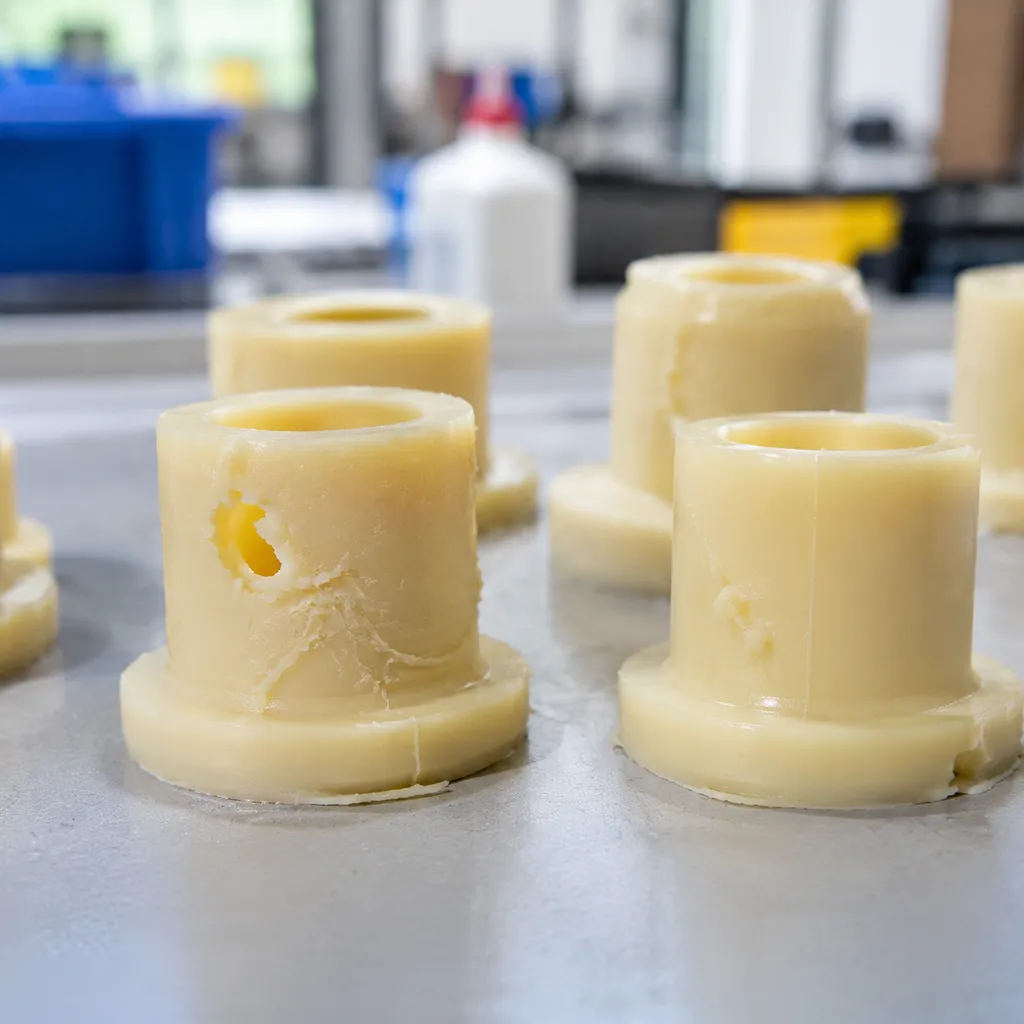
Understanding Wax Injection Defects
Precision investment casting relies entirely on the accuracy of the initial wax pattern. Any physical flaw in the wax transfers directly into the ceramic shell and appears on the finished metal part. When managing pattern production, I treat the wax injection molding process as the first line of defense against downstream scrap.
Why Wax Quality and Injection Parameters Matter
Wax is a sensitive material that reacts quickly to small shifts in temperature, pressure, and flow rates. Maintaining tight control over these variables prevents the root causes of major wax pattern defects.
- Temperature Consistency: Wax viscosity shifts drastically with slight thermal variations, influencing how the melt fills complex die geometry.
- Injection Pressure Profile: Low pressure causes voids, while excessive pressure forces parting lines apart.
- Flow Rate Control: Uncontrolled velocity introduces air into the stream, leading directly to air entrapment in wax patterns.
| Process Parameter | Primary Role | Risk of Poor Control |
|---|---|---|
| Wax Temperature | Viscosity & fluidity control | Short fills or excessive volumetric shrinkage |
| Injection Pressure | Cavity filling & packing | Flash, parting line separation, or incomplete geometry |
| Flow Velocity | Laminar cavity filling | Internal air bubbles, turbulence, and cold shuts |
| Die Clamping Pressure | Mold seal integrity | Parting line flash and dimensional variation |
The Impact of Defects on Investment Casting Accuracy
Defective wax patterns compromise overall casting yield and inflate production costs. A flawed pattern inevitably generates a flawed casting:
- Direct Shell Failure: Surface bubbles and air pockets cause weak spots in the ceramic slurry coating, risking metal breakouts during pouring.
- Excess Finishing Labor: Flash on the parting line requires manual scraping, which increases cycle time and risks damaging critical surfaces.
- Out-of-Tolerance Castings: Uncontrolled shrinkage and dimensional instability lead to assembly failures and scrapped casting runs.
Strict process repeatability at the injection stage eliminates downstream machining adjustments, guarantees casting geometry, and maintains stable production costs.
Troubleshooting Bubbles in Wax Patterns

Surface blisters and internal voids ruin wax pattern integrity fast. When producing patterns for investment casting, trapped air inside the cavity leads directly to defective ceramic shells and metal scrap downstream.
Common Causes of Trapped Air and Turbulence
Air entrapment in wax patterns typically stems from two culprits: Turbulent Flow: Injecting liquid or paste wax at excessive velocity creates vortexes that pull surrounding air into the stream. Paste Aeration: Insufficient de-aeration in the reservoir introduces micro-bubbles into the wax blend before it even reaches the nozzle. Blind Cavities: Die pockets without an escape path trap pocketed air as the wax front advances.
Adjusting Injection Pressure and Venting Techniques
We eliminate air entrapment by profiling injection speed and opening clear escape routes: Profile Injection Velocity: Start with a slow fill rate to establish laminar flow through the gates, ramping up pressure only to pack the pattern. Inspect Die Venting: Ensure parting line vents measure between 0.02 mm and 0.05 mm deep—wide enough to purge air without letting wax flash out. Optimize Machine Parameters: Follow a systematic wax injection machine troubleshooting guide for fast fixes to balance dwell pressures and prevent cavity back-pressure buildup.
Best Practices for Mold Release Application
Excess mold release agent is a frequent, overlooked driver of surface bubbles: Avoid Pooling: Liquid release agent trapped in sharp corners boils or reacts under hot wax, forming gas pockets that mimic air traps. Apply Light, Uniform Coats: Use a fine aerosol or automated atomizing spray, wiping away puddles with a lint-free cloth before closing the die. Standardize Frequency: Reapply release only every few cycles rather than every shot to maintain clean tooling surfaces and sharp pattern detail.
Solving Short Fill in Wax Patterns
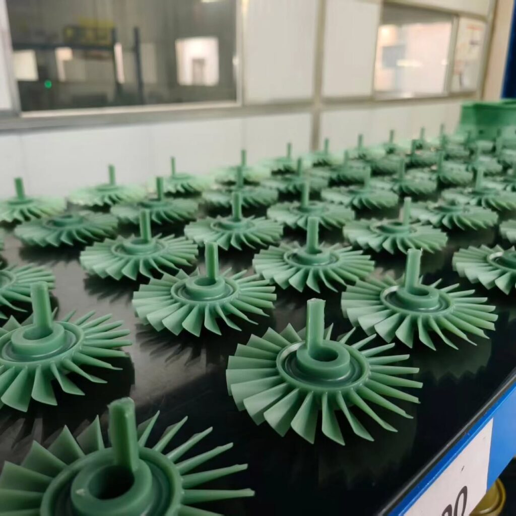
A short fill happens when injected wax freezes before completely filling every corner of the die cavity. When we pull a pattern with rounded edges, missing thin walls, or incomplete bosses, downstream casting fails before it even starts. Eliminating short fill in wax injection requires balancing thermal conditions, injection dynamics, and tooling geometry.
Identifying Flow Restrictions and Temperature Drops
Premature chilling is the primary culprit behind incomplete fills. When molten or paste wax hits a cold tool surface, it forms a frozen skin that chokes off the flow path.
To pinpoint where the wax stalls: Check tool surface temperature: Cold spots in the die cause rapid heat loss, especially in complex geometries or thin ribs. Inspect air vents: If air cannot escape ahead of the wax front, backpressure halts filling. Clean out residual wax or release agents clogging vent lines. Verify nozzle seating: A misaligned injection nozzle creates pressure loss and turbulence at the die sprue, reducing actual cavity filling pressure.
Optimizing Wax Temperature and Cycle Times
Consistent flow depends heavily on maintaining the correct wax viscosity and pressure curves throughout the injection cycle.
- Wax conditioning: Keep reservoir and nozzle temperatures strictly calibrated. Raising temperature slightly reduces viscosity and aids flow into intricate profiles, but excessive heat increases shrinkage and cycle time.
- Injection speed and pressure: Ramp up injection velocity to drive wax into thin-walled sections before it congeals. Follow this with sufficient holding pressure to pack out distant features.
- Dwell time balance: Ensure the hold time holds pressure just long enough for the gates to freeze, preventing backflow without unnecessarily extending cycle times.
Ensuring Proper Runner and Gate Design
Tooling design determines how smoothly wax enters the cavity. If gating is too restrictive, even perfect machine parameters cannot prevent a short fill. When producing complex patterns, such as delicate housings or impellers destined for A356 aluminum alloy specifications and properties, proper gate placement makes all the difference.
- Gate sizing: Enlarge restrictive gates and runners to reduce flow resistance and prevent premature gate freeze-off.
- Flow progression: Position gates so wax flows naturally from thick sections into thinner walls, avoiding sudden directional shifts.
- Multi-gate balancing: On multi-cavity dies, balance runner lengths and cross-sections so all cavities fill at the exact same rate under identical pressure.
Eliminating Flash in Wax Patterns
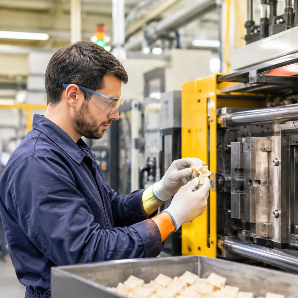
Parting line flash wastes wax, eats up labor hours in hand-finishing, and disrupts downstream processes. When liquid or semi-solid wax forces its way between mating die surfaces, the resulting thin fins indicate that injection pressure has overcome tool retention. Keeping wax patterns clean and flash-free requires balancing mechanical force with disciplined tool care.
Reasons for Parting Line Separation
Flash almost always stems from a loss of hydraulic or mechanical balance. The most common triggers include:
- Excessive Injection Pressure: Spiking pressure at the end of the fill stroke forces the die faces apart before the wax solidifies.
- Wax Overheating: High wax temperatures lower viscosity, allowing material to seep into microscopic gaps between die halves.
- Parting Line Contamination: Dried wax build-up, metal chips, or debris hold the mold plates slightly open, creating an easy escape path for pressurized wax.
Checking Clamping Force and Mold Integrity
We treat proper clamping pressure as the first line of defense against flash:
- Verify Machine Clamping Tonnage: Ensure the machine’s die clamping pressure matches the projected surface area of the pattern cavity and gating system.
- Inspect Mold Platen Parallelism: Uneven clamping forces one side of the die to gap while the other takes all the load. Use pressure-sensitive film periodically to confirm uniform contact across the entire parting face.
- Match Pressure Profiles: Lower the holding pressure just as the cavity reaches 95% capacity to prevent pressure surges against the parting line. Maintaining strict dimensional integrity here is critical to meet rigorous casting quality standards for reliable metal parts.
Maintenance Tips for Die Faces and Alignment
Proper tooling maintenance prevents edge degradation and preserves tight seals:
- Use Soft Cleaning Tools: Never clean die faces or vents with steel scrapers or hard picks. Use brass, copper, or hardwood scrapers alongside residue-free solvents to protect parting edges.
- Check Guide Pins and Bushings: Worn guide pins cause mold halves to misalign under pressure. Replace loose bushings immediately to maintain tight registration.
- Inspect Parting Line Edges for Roll-Over: Over-clamping on contaminated dies rolls the cavity edges inward. Stone parting surfaces flat and re-machine worn parting lines to eliminate gaps before they generate recurring wax pattern defects.
Correcting Dimensional Variation

Controlling pattern dimensions is one of the toughest challenges in the wax injection molding process. When wax patterns pull out of tolerance, the resulting metal castings mirror those errors directly. Addressing dimensional variation requires strict control over cooling rates, dwell time, and environmental conditions.
Factors Affecting Wax Shrinkage and Cooling Rates
Wax expands when heated and contracts as it solidifies. The degree of volumetric contraction depends directly on thermal management and mechanical pressure:
- Volumetric Shrinkage: High injection temperatures expand the wax excessively, leading to significant sink marks and shrinkage as it cools in the die.
- Holding Pressure and Dwell Time: If you release holding pressure before the gate freezes, molten wax flows back toward the nozzle, causing internal voids and dimensional collapse.
- Section Thickness Variations: Thick sections retain heat far longer than thin walls, creating uneven cooling rates that lead to internal stress and warpage.
For intricate geometries, specialized methods for fixing wax pattern shrinkage in complex molds ensure critical tolerances remain stable across every cycle.
How to Achieve Consistent Pattern Sizing
To maintain repeatable dimensions from run to run, focus on stabilizing your process parameters:
- Calibrate Holding Time: Keep the pattern under sustained holding pressure until the gate solidifies completely to pack out the cavity.
- Standardize Wax Conditioning: Maintain consistent paste or liquid wax conditioning in the reservoir. Inconsistent viscosity directly alters volumetric fill.
- Use Post-Ejection Support Fixtures: Place hot or heavy patterns onto cooling fixtures or setter blocks immediately after ejection to prevent sagging and thermal distortion while cooling to room temperature.
Managing Ambient Temperature and Mold Cooling Cycles
Thermal fluctuations in the tooling and shop environment directly influence shrinkage and dimensional stability:
| Variable | Target Control Measure | Impact on Dimensions |
|---|---|---|
| Tooling Temperature | Integrated cooling channels (water circuits) | Prevents hot spots that cause localized sinking |
| Ambient Shop Climate | Controlled storage and injection room temperature | Stops seasonal shifts from expanding or shrinking patterns |
| Cycle Cadence | Automated, uniform dwell and open times | Delivers identical cooling curves for every single shot |
Locking in steady mold temperatures and standardized dwell times eliminates the thermal swings that drive wax pattern defects and dimensional variation.
FAQs: Wax Injection Troubleshooting
How do I choose the right wax temperature for my machine?
Finding the target temperature depends on your specific pattern wax formulation, pattern geometry, and whether you run liquid or paste wax. For solid, defect-free patterns, we aim for the lowest temperature that still completely fills the cavity without causing flow lines.
- Check the wax transition state: Paste wax operates just below the complete liquidus point (semi-solid state), which significantly reduces volumetric shrinkage and sink marks. Liquid wax requires higher temperatures to maintain low viscosity across thin walls.
- Match tooling complexity: Thin-walled patterns require higher flow rates and slightly elevated temperatures to avoid freeze-off, while thick cross-sections benefit from lower temperatures to stabilize dimensions.
- Maintain tight thermal bands: Variations of just 1–2°C can shift your process from short fills to parting line flash. Operating a reliable wax injection machine with PID control ensures consistent reservoir, hose, and nozzle temperatures throughout long production shifts.
| Wax State | Typical Consistency | Primary Advantage | Best Used For |
|---|---|---|---|
| Paste Wax | Semi-solid, buttery | Minimal shrinkage, faster dwell times | Medium-to-heavy sections, tight tolerances |
| Liquid Wax | Fully melted, low viscosity | High flowability in complex cavities | Extremely thin sections, intricate detailing |
Can mold design affect how often I get bubbles?
Yes. Mold design directly dictates how air exits the cavity as the pattern wax enters. In fact, poor tooling geometry is the primary cause of persistent air entrapment in wax patterns.
- Improper venting: Without adequate parting line vents or porous vent plugs at the highest points of the cavity, incoming wax compresses air into pockets, creating surface blisters or hollow voids.
- Turbulent runner geometry: Sharp 90-degree turns and abrupt changes in runner cross-sections induce turbulence. This churns air directly into the wax stream before it enters the cavity.
- Gate location: Gates must be positioned to promote laminar flow from the thickest sections toward the thinnest areas. Off-center or poorly directed gates cause the wax flow front to fold over itself, trapping air against the tool walls.
What is the quickest way to stop flash on a wax die?
When flash suddenly appears on your parting lines or core pulls, take these immediate troubleshooting steps:
- Drop secondary injection pressure: Lower the holding pressure first. The wax may be filling fine, but excessive packing pressure at the end of the stroke is forcing the die halves apart.
- Inspect and clean parting faces: Shut down the cycle and inspect the die faces. Even a microscopic film of hardened wax or debris prevents the mold halves from sealing flush.
- Verify die clamping pressure: Check that the hydraulic or pneumatic clamping unit on your wax injection machine for investment casting delivers enough tonnage to counter the projected cavity area under full injection load.
- Check guide pin and bushing wear: Misalignment between mold halves leads to uneven pressure distribution across the parting line, letting wax seep out through the loose side.


 English
 Russian
 German