

2026年11月8日
Master wax temperature and injection pressure control for investment casting with practical settings troubleshooting tips and defect prevention

Wax Temperature and Injection Pressure Control Guide Overview
In precision investment casting, inconsistency is the primary driver of scrap. Our integrated digital control unit is engineered to stabilize the injection process, transforming the way you handle both paste and liquid waxes. By focusing on thermal precision and hydraulic accuracy, we help foundries eliminate costly pattern shrinkage and cavitation.
Core System Advantages
Our controller provides the granular control necessary to achieve repeatable, high-quality patterns regardless of tooling complexity.
| Feature | Technical Benefit |
|---|---|
| Thermal Stability | ±0.2°C variance ensures consistent wax viscosity. |
| Pressure Profiling | Dynamic multi-stage cycles prevent structural defects. |
| Recipe Engine | Pre-calibrated parameters for complex tool geometries. |
| Defect Mitigation | Actively eliminates shrinkage and cavitation voids. |
Precision Through Engineering
We designed this system to act as the "brain" of your injection process. By utilizing a built-in parameter recipe engine, operators can load validated settings for specific tool geometries, ensuring that wax rheology remains consistent from the first shot to the last. This removes the guesswork from setting up new jobs and provides the stability needed to meet demanding aerospace and industrial tolerances.
By automating the transition between fill and dwell stages, our technology addresses the core mechanical challenges of investment casting, ensuring every pattern is dimensionally accurate and free of surface defects.
Multi-Zone Thermal PID Controller Setup
Thermal instability across the wax conditioning line is one of the most frustrating sources of scrap in lost wax casting. When temperatures drift even two degrees between the conditioning tank and the injection tip, wax viscosity shifts unpredictably. The result on the foundry floor is immediate: premature solidification in thin pattern sections, poor surface finish, or excessive pattern sink. We engineered our multi-zone thermal PID controller setup to solve this exact problem, creating seamless, zone-by-zone thermal equilibrium throughout the entire injection circuit.
Independent Closed-Loop PID Control from Reservoir to Injection Nozzle
A single thermal zone cannot regulate wax correctly. Heat dissipates rapidly at the injection tip while building up inside the reservoir. Our closed-loop temperature control unit segments the entire wax path into independently managed heating zones:
- Bulk Conditioning Reservoir: Keeps raw wax molten and uniform at base paste or liquid holding temperatures.
- Transfer Manifolds and Pumping Lines: Compensates for flow resistance and ambient heat loss during wax movement.
- Injection Cylinder Chamber: Stabilizes wax volume prior to ram displacement to ensure homogeneous density.
- Active Injection Nozzle: Delivers targeted, rapid-response heating directly at the die interface to prevent tip-freeze without overheating the wax core.
By pairing each zone with an isolated digital feedback loop, we isolate thermal disturbances. When evaluating a new wax injection machine with PID control, isolating these individual thermal zones is what keeps viscous paste wax flowing smoothly without cold slugs blocking runner gates.
Dual Class-A PT100 RTD Sensor Placement and Thermal Gradient Regulation
Surface readings rarely reflect core wax temperatures. Relying solely on heater jacket sensors leads to massive temperature lags, causing the system to overheat the jacket while the center of the wax channel remains cold.
To eliminate thermal gradients, we position dual Class-A PT100 RTD sensors at strategic locations across each zone:
| Sensor Role | Placement Location | Primary Function |
|---|---|---|
| Jacket Monitor | Embedded in aluminum heating plate | Regulates element power and prevents overshoot |
| Direct Melt Sensor | Submerged directly in the wax flow stream | Reads actual wax rheology temperature within ±0.2°C |
| Nozzle Tip Sensor | 5mm from the injection orifice | Prevents skin chill and eliminates gate freeze during cycle pauses |
The PID algorithm computes the delta between the element and the melt, dynamically throttling power before the thermal wave can overshoot your recipe setpoint.
Anti-Thermal Shock Heating Elements Stop Wax Degradation and Carbonization
Foundry waxes are delicate organic compounds. Subjecting them to high-watt-density heating coils scorches the material, breaking down polymer chains and producing carbonized grit. These carbon flakes lodge in runner bars or pattern surfaces, causing non-metallic inclusions and shell spalling during burnout.
We utilize custom surface-contact, low-watt-density heating blankets and cast-in elements designed for soft thermal delivery:
- Low Surface Watt Density: Heaters operate at under 2.5 W/cm², distributing energy over maximum surface area rather than blistering the wax contact wall.
- Ramp-Rate Limiting: Soft-start warm-up curves gradually bring cold wax up to temperature, preventing localized boiling and localized polymer shear.
- No Hot-Spot Geometry: Elimination of dead corners inside the injection cylinder ensures wax cannot stagnate, degrade, or form hardened crusts over extended shifts.
This thermal architecture provides the strict process repeatability required by high-spec investment casting operations, ensuring every shot enters the tooling at identical viscosity and density.
Hydraulic Wax Injection Pressure Control and Profiling
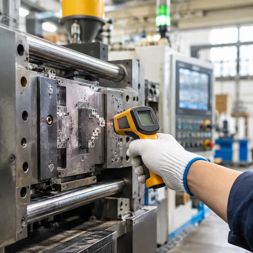
Foundry scrap often comes down to a blunt pressure profile: inject too hard and you blow past the parting line to create flash; inject too soft or drop pressure too early and heavy sections develop sink marks. We solve this on our hydraulic wax injection machine systems by splitting the cycle into a responsive, multi-stage pressure curve.
Two-Stage Injection Sequence: Fill vs. Dwell
Balancing cavity velocity against volumetric shrinkage requires two distinct operating phases:
- Stage 1: Primary Cavity Fill: High-flow, low-to-medium pressure rapidly drives paste or liquid wax into the die, filling intricate walls before the material skins over or chills.
- Stage 2: Packing Dwell Pressure: The system instantly throttles flow and shifts to an elevated holding pressure. This continuous packing force feeds fresh wax into the solidifying core to counteract volumetric shrinkage without parting the die halves.
| Phase | Target Action | Hydraulic Response | Primary Benefit |
|---|---|---|---|
| Initial Fill | Dynamic volumetric fill | High flow / Regulated low pressure | Prevents flow lines, non-fills, and flash |
| Packing Dwell | Shrinkage compensation | Micro-flow / Stepped holding pressure | Eliminates sink marks, cavitation, and voids |
High-Speed Servo Proportional Valves
Mechanical delays in standard hydraulic blocks cause pressure spikes that damage tooling and generate inconsistent pattern weights. We utilize high-speed servo proportional valves delivering a 15ms dynamic response time.
This closed-loop feedback instantly cushions the switchover from rapid cavity filling to packing dwell. The valve trims pressure output in real time, absorbing line shock and delivering smooth, repeatable cycles regardless of oil temperature fluctuations.
Volumetric Flow Control
Controlling volumetric flow keeps the wax front advancing at a laminar, uniform rate. Regulating both flow volume and transition timing prevents the sudden velocity surges that cause air entrapment and surface blisters. By maintaining constant pressure during the critical cooling phase, our systems stop core shrinkage and keep pattern dimensions repeatable from the first shot of the shift to the last. Understanding these parameters helps eliminate standard wax injection defects before patterns ever make it to the assembly tree.
Smart Injection Parameter Controller and Data Logging
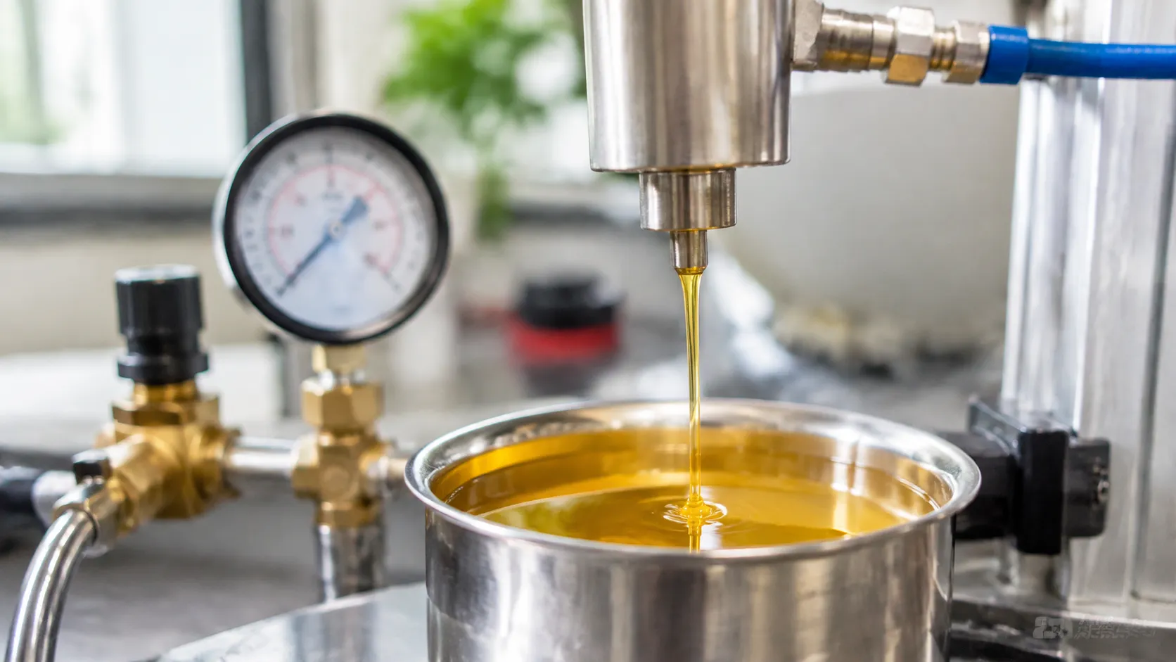
Relying on manual operator logbooks to track cycle consistency creates blind spots on the foundry floor. When pattern dimensions drift between shifts, finding the root cause without historical injection data wastes hours of press time. Our investment casting parameter controller automates process regulation and logs every critical injection metric down to the millisecond.
Pre-Loaded Recipe Management for Wax Rheology
Tool geometries demand tailored flow dynamics. A thick turbine blade hub behaves differently in the die than a razor-thin structural bracket. Our system stores and deploys pre-calibrated parameter profiles based on mold geometry:
- Wax Rheology Matching: Instantly balances hydraulic velocity against wax viscosity to fill thin walls without premature chilling.
- Geometry-Specific Dwell: Applies custom hold times mapped directly to mold cross-sections, stopping shrinkage before it starts.
- One-Touch Die Changeovers: Operators select the part number on the interface, loading validated thermal curves and injection pressure sequences in seconds.
| Parameter Variable | Thin-Walled Castings (<3mm) | Heavy-Section Tooling (>15mm) |
|---|---|---|
| Injection Velocity | High volumetric fill | Controlled laminar flow |
| Primary Pressure | Moderate fill to stop flash | Low initial velocity to avoid jetting |
| Dwell Packing Time | Short (3–8 seconds) | Extended multi-stage (15–45 seconds) |
| Viscosity Window | Higher flow / liquid paste | Semi-solid paste state |
Real-Time Telemetry: Temperature vs Cycle Time and Pressure vs Stroke
We eliminate guesswork by displaying live process curves directly on the shop-floor terminal. Our unit continuously tracks two core telemetry profiles:
- Pressure vs. Stroke: Verifies the dynamic transition point between cavity fill and secondary packing pressure, preventing core pin deflection.
- Temperature vs. Cycle Time: Monitors nozzle and reservoir stability through each injection stroke to catch thermal decay before wax enters the parting line.
Automated Deviation Alerts and Lot Traceability
Meeting high-integrity production benchmarks—such as casting quality standards for reliable metal parts—requires complete process accountability. If reservoir temperature fluctuates by more than ±0.2°C or hydraulic pressure spikes past your target envelope, our controller flags the cycle immediately:
- Automated Press Interlocks: Rejects out-of-spec cycles and halts the cycle to stop defective wax patterns from reaching the assembly room.
- Complete Lot Serialization: Exports time-stamped datasets per shot, logging pressure profiles, peak temperatures, and dwell durations.
- Compliance-Ready Architecture: Delivers the audit trails required for titanium investment casting for aerospace and medical parts, ensuring full traceability from raw pattern to finished component.
Solving Wax Pattern Defects with Precise Temperature and Pressure Control
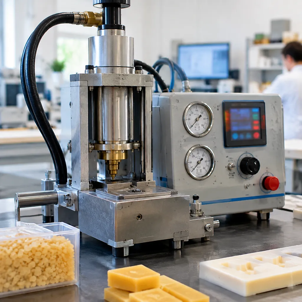
Dimensional scrap, unexpected cavitation, and endless manual rework drain foundry profits fast. When a pattern comes out deformed, the problem almost always traces back to unstable melt states or erratic hydraulic force. We engineered our process controls to tackle pattern defect elimination right inside the die, cutting out secondary rework before the pattern ever reaches the treeing line. Pairing strict parameter discipline with a precision casting solution with silica sol process ensures your wax assemblies reliably meet rigorous dimensional tolerances.
Stopping Sink Marks and Cavitation with Dwell Sequencing
Heavy cross-sections naturally cool slower than thin walls, pulling wax inward and leaving sunken areas or internal voids. The Root Cause: Wax shrinks significantly as it shifts from liquid/paste to solid. If pressure drops before the gate freezes, molten material draws away from thick sections. Our Solution: We run a high-pressure dwell sequence using a closed-loop injection dwell pressure controller. Once the mold cavity fills, the system maintains packing pressure, forcing fresh wax into the core to compensate for volumetric contraction until the gate solidifies completely.
Eliminating Mold Flash Through Low-Pressure Filling
Flashing along parting lines ruins fine details and requires tedious trimming that risks damaging thin profiles. The Mechanism: Flashing happens when injection peak pressure overwhelms the machine clamp force or when liquid wax hits the tooling parting line with excessive velocity. Our Control Fix: We split the cycle into a low-pressure volumetric filling stage followed by an instant transition to packing. Integrated clamp monitoring interlocks the hydraulic wax injection pressure control, preventing pressure spikes from exceeding the die’s mechanical clamping limits.
| Common Defect | Primary Mechanical/Thermal Cause | Our Control Correction |
|---|---|---|
| Sink Marks | Gate freeze-off before complete volumetric packing | Multi-stage dynamic dwell pressure profiling |
| Parting Flash | Pressure spikes exceeding tooling clamp tonnage | Low-pressure cavity filling with clamp tonnage interlock |
| Cold Shuts | Premature chilling during cavity transit | Synchronized nozzle thermal zones to eliminate freeze skin |
| Surface Blisters | Turbulent flow trapping air against die walls | Closed-loop proportional velocity profiles |
Preventing Flow Lines and Cold Shuts
Flow lines and cold shuts occur when two streams of wax meet after partially solidifying, leaving weak seams and surface blemishes across the pattern. Thermal Synchronization: We eliminate premature chilling by locking nozzle temperature directly to reservoir thermal zones. Seamless Infill: Keeping the wax at an exact, homogeneous temperature prevents freeze skin from developing during injection, ensuring adjoining flow fronts merge into a single solid structure.
Fixing Air Entrapment and Surface Blisters
Blisters and internal bubbles ruin structural integrity and show up as catastrophic scrap later in the shell room. Velocity Profiling: Rapid, uncontrolled injection forces air into pockets rather than venting it through parting lines. Controlled Flow Rates: We ramp flow speed dynamically—starting slow through the gate, accelerating across open geometry, and easing off at final fill. This linear flow front drives air straight out of the exhaust vents without foaming or surface blistering.
Wax Injector Retrofit Package and System Compatibility
Upgrading outdated injection machinery does not require scrapping solid structural iron. We engineered our wax injector retrofit package as a modular solution to replace drifting analog dials, obsolete relay racks, and failing manifold valves on existing shop-floor equipment. By modernizing the control heart of your machine, you achieve tight process control without the capital cost of a completely new press.
Drop-In Upgrades for Legacy Injection Presses
Our pre-wired control enclosures interface directly with existing power drops and mechanical frames. We tailor mounting hardware and wire looms to minimize installation downtime across all standard press architectures:
- C-Frame Wax Presses: Direct bolt-on consoles that restore throat access while adding multi-stage hydraulic profiling.
- 4-Pillar Vertical Presses: Integration with moving platen position encoders to tie clamping stroke directly into injection sequencing.
- Horizontal Wax Injectors: Modernized hydraulic proportional valve blocks that slide into existing power-pack footprints.
Die Clamping System Interfacing
Safe, repeatable injection requires zero platen movement during peak dwell. Our precision wax injection system monitors and interlocks with any die clamping arrangement:
- Hydraulic Clamping: Closed-loop pressure transducer integration to prevent injection before clamping tonnage is verified, eliminating die separation.
- Pneumatic Toggle Clamps: Digital limit-switch verification ensuring complete mechanical lockup before the injection valve opens.
- Manual Cam Clamps: Magnetic interlock sensors that prevent shot initiation until manual toggles are firmly seated.
Automation and Robotic Cell Integration
For high-volume operations producing components like turbine blades or tooling for cobalt-based casting for heat, wear, and corrosion resistance, consistency hinges on automation. Our automated wax pattern molding controller acts as the central command node via standardized industrial I/O:
- Robotic Extraction Arms: Handshake signals synchronize vacuum gripping, core pull confirmation, and part ejection routines.
- Automated Pattern Assembly: Upstream conveyors and sprue welding cells pull cycle completion data to balance production pacing.
- Safety Interlocks: Dual-channel safety circuits tie light curtains, emergency stops, and interlocked perimeter guarding straight into the primary PLC.
Technical Specifications of the Wax Control System
We engineered our precision wax injection system to meet the rigorous demands of modern foundries. By integrating robust PLC architecture with high-fidelity thermal and pressure sensors, we provide the stability required for aluminum investment casting and complex alloy production.
Performance and Control Capabilities
| Feature | Specification Details |
|---|---|
| Thermal Range | Ambient to 100°C (±0.2°C stability) |
| Sensor Type | Dual Class-A PT100 RTD |
| Pressure Resolution | 0.1 bar (Servo-proportional control) |
| Interface | 10-inch Industrial HMI Touchscreen |
| Communication | Modbus TCP/IP, Profinet, EtherCAT |
| Logic Control | High-speed PLC with multi-stage recipe engine |
System Architecture Highlights
- Thermal Regulation: Multi-zone closed-loop PID control ensures uniform heat distribution from the reservoir to the injection nozzle, preventing wax degradation and carbonization.
- Injection Precision: Our hydraulic and pneumatic control units feature high-speed servo valves, achieving a 15ms dynamic response time to maintain consistent volumetric flow.
- Data Integration: The system supports standard fieldbus protocols, allowing seamless integration with existing factory automation, robotic cells, and centralized ERP data logging for complete lot traceability.
- Reliability: Built to withstand harsh foundry environments, our control panels utilize hardened circuitry and modular components, ensuring consistent performance even under heavy-duty casting cycles.
Industrial Compliance and Factory Acceptance Testing

We ensure our systems meet rigorous global safety and quality benchmarks, because we know that unreliable control panels are a liability on any production floor. Every unit we build adheres strictly to CE, UL 508A, and ISO 9001:2015 industrial control panel standards, guaranteeing that your hardware is ready for seamless integration into a compliant manufacturing environment.
Before your equipment ever hits your loading dock, it undergoes comprehensive Factory Acceptance Testing (FAT) to ensure consistent performance from day one. Our standard verification protocols include:
- Thermal Uniformity Mapping: Detailed sensor analysis to ensure heating elements maintain consistent temperatures across the entire system.
- Pressure Step-Response Verification: High-speed testing to validate that your injection pressure control reacts instantly to command signals.
- Custom Tooling Evaluations: We analyze your specific die configurations to fine-tune system parameters, ensuring your casting process methods align with your output requirements.
- Application Engineering Support: Expert guidance to help you optimize the synergy between wax rheology and your specific injection machine hardware.
By focusing on these industrial-grade validation steps, we remove the guesswork from your installation, providing a stable foundation for high-precision investment casting.
Frequently Asked Questions About Wax Temperature and Injection Pressure Control
How does closed-loop multi-zone heating prevent pattern shrinkage?
Wax shrinks dramatically when it transitions from liquid to solid. Inconsistent temperatures across the delivery line create uneven volumetric contraction, which leads straight to sink marks and dimensional scrap.
Our multi-zone thermal PID controller maintains continuous closed-loop feedback from the conditioning reservoir directly to the injection nozzle tip. By keeping wax within a tight ±0.2°C window, we eliminate localized hot spots and control the solid-to-liquid fraction. This ensures uniform volumetric density throughout the cavity, making pattern dimensions predictable run after run.
Can we retrofit this control unit onto older hydraulic wax injection presses?
Yes. We engineered our wax injector retrofit package to modernize legacy C-frame, 4-pillar, and horizontal presses without replacing existing mechanical frames.
- Direct Valve Interfacing: Replaces manual needle valves with digital servo proportional valves for modern hydraulic wax injection pressure control.
- Universal PLC Architecture: Bridges easily with legacy electrical cabinets, pneumatic clamps, and hydraulic power units.
- Turnkey Modernization: Upgrades older units to match the performance standards found on a modern wax injection machine for investment casting.
What is the ideal pressure sequence for thin-walled versus heavy-section patterns?
Different part geometries require distinct dynamic pressure profiling to balance rapid fill times against volumetric shrinkage:
| Feature Geometry | Primary Fill Pressure | Dwell / Packing Pressure | Focus Area |
|---|---|---|---|
| Thin-Walled (<3 mm) | High (4.5–6.0 MPa) | Low (1.5–2.5 MPa) | Fast fill prevents premature freezing and flow lines before cavity pack-out. |
| Heavy-Section (>12 mm) | Moderate (2.5–3.5 MPa) | Extended High (4.0–5.5 MPa) | Prolonged dwell feeds volumetric shrinkage as the core cools, stopping cavitation. |
Using an independent injection dwell pressure controller allows our system to switch between primary fill and packing stages within 15 milliseconds, protecting thin sections from flash while fully feeding heavy bosses.
How does the digital recipe manager handle different wax rheology profiles?
Paste waxes, filled pattern waxes, and straight hydrocarbon blends flow differently under shear and thermal loads. Understanding these behavioral shifts is critical when evaluating how to choose the right wax injection machine configuration for your foundry.
Our digital controller stores pre-calibrated injection recipes tied directly to specific tooling and wax blends:
- Viscosity Compensation: Adjusts individual zone temperatures to maintain target viscosity without overheating thermal-sensitive fillers.
- Dynamic Flow Profiling: Scales injection velocity curves to prevent flow turbulence, air entrapment, and premature wax chilling.
- Automated Clamping Limits: Ties injection pressure ceilings directly to clamp tonnage limits, preventing mold separation across varying viscosities.

 English
 Russian
 German