
2026年10月15日
Explore reliable turbine engine component solutions designed for durability precision performance and efficient operation in demanding aerospace appli
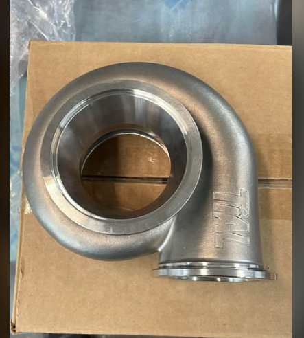
Core Turbine Engine Component Categories
Every high-performance turbine engine component must endure extreme mechanical, aerodynamic, and thermal stresses. We categorize these critical parts into distinct functional zones to streamline sourcing, inspection, and maintenance workflows across commercial and industrial operations.
| Engine Section | Key Assemblies | Primary Engineering Demands |
|---|---|---|
| Cold Section | Fan blades, compressor rotors, stator vanes | Aerodynamic efficiency, high strength-to-weight ratio, impact resistance |
| Hot Section | Combustor liners, turbine blades, nozzle guide vanes | Ultra-high temperature tolerance, creep resistance, thermal cycling stability |
| Structural & Rotating | Main shafts, turbine discs, bearings, dynamic seals | Rotational integrity, fatigue resistance, tight dimensional tolerances |
| Exhaust & Propulsion | Tail cones, exhaust nozzles, augmenters, thrust reversers | Thermal expansion management, acoustic damping, pressure retention |
Cold Section Assemblies: Fan Blades, Compressor Rotors, and Stators
The cold section manages incoming airflow and multi-stage pressure elevation: Fan Blades: Direct large air volumes into core and bypass ducts while resisting foreign object damage. Compressor Rotors: Accelerate air through sequenced rotating stages to optimize pre-combustion density. Stator Vanes: Stationary airfoils that stabilize and redirect airflow between rotating stages to prevent aerodynamic stall.
Hot Section Essentials: Combustion Liners, Turbine Blades, and Guide Vanes
Operating downstream of fuel delivery, these parts handle peak combustion temperatures: Combustion Liners: House the primary combustion zone and regulate flame stability under high thermal loads. Nozzle Guide Vanes: Direct high-energy, expanding gas streams onto the turbine rotor at precise approach angles. Turbine Blades: High-pressure turbine blades extract thermal energy to power the forward compressor and fan drive.
Structural and Rotating Hardware: Shafts, Discs, Bearings, and Dynamic Seals
Mechanical power transmission relies on structurally validated rotating hardware: Shafts and Discs: Transfer massive torque loads between turbine stages and front-end compressors. Bearings: Support high-RPM rotating shafts with minimal frictional losses under heavy axial and radial thrust. Dynamic Seals: Prevent high-pressure air and lubrication leaks between moving shafts and stationary housings.
Exhaust and Propulsion Hardware: Tail cones, Augmenters, and Thrust Reversers
The aft section directs gas discharge to deliver final operational thrust: Tail Cones: Smooth core exhaust exit lines to minimize aerodynamic drag and backpressure. Augmenters and Nozzles: Regulate gas exit velocity and expansion to maximize thrust efficiency. Thrust Reversers: Mechanically redirect exhaust gas forward during ground deceleration to reduce brake wear.
Materials Used in Turbine Engine Component Manufacturing
Every critical turbine engine component must survive extreme mechanical loads, aggressive gas paths, and intense thermal cycling. We select advanced aerospace alloys and protective barrier systems engineered specifically for each operational zone of the engine.
Nickel-Based Superalloys for Ultra-High Temperature Resistance
In the combustion and high-pressure turbine sections, gas temperatures often exceed the melting point of basic metals. We rely on a premium nickel-based alloy for high strength and corrosion resistance to maintain mechanical integrity under heavy stress: Thermal Endurance: Retains yield strength and structural stability above 1,000°C. Creep Resistance: Resists dimensional distortion during prolonged high-load cycles. Key Parts: High-pressure turbine blades, combustor liners, and rotating turbine discs.
Titanium Alloys for High-Strength, Lightweight Cold Section Parts
Weight reduction directly boosts thrust-to-weight efficiency in the cold section. We utilize aerospace-grade titanium alloys to optimize rotating inertia: Exceptional Strength-to-Weight Ratio: Cuts rotational mass while withstanding severe centrifugal loads. Fatigue Resistance: Delivers high cycle fatigue life against turbulent inlet airflow. Key Parts: Fan blades, compressor rotor assemblies, and forward casing rings.
Cobalt Alloys for Superior Hot Corrosion and Wear Resistance
Where unlubricated friction, sulfidation, and high temperatures intersect, cobalt alloys outperform alternatives. Utilizing cobalt-based casting for heat, wear, and corrosion resistance ensures long part life under aggressive conditions: Fretting and Wear Protection: Eliminates galling at contact points and interlock surfaces. Chemical Stability: Resists hot gas corrosion and sulfur oxidation without rapid degradation. Key Parts: Nozzle guide vanes, seal segments, and static stage hardware.
Ceramic Matrix Composites (CMCs) and Thermal Barrier Coatings (TBC)
Pushing operational temperatures higher requires surface shielding and composite materials: Thermal Barrier Coatings (TBC): Plasma-sprayed yttria-stabilized zirconia drops base metal surface temperatures by over 100°C. Ceramic Matrix Composites (CMCs): Provides one-third the weight of nickel superalloys with higher temperature capabilities, reducing cooling air requirements across the hot section.
Manufacturing and Quality Standards for Turbine Engine Parts
Every turbine engine component operates under brutal mechanical loads and extreme temperatures. To guarantee long-term airworthiness and zero-defect performance, our production lines combine advanced forming techniques with strict international quality controls.
Investment Casting and Directional Solidification
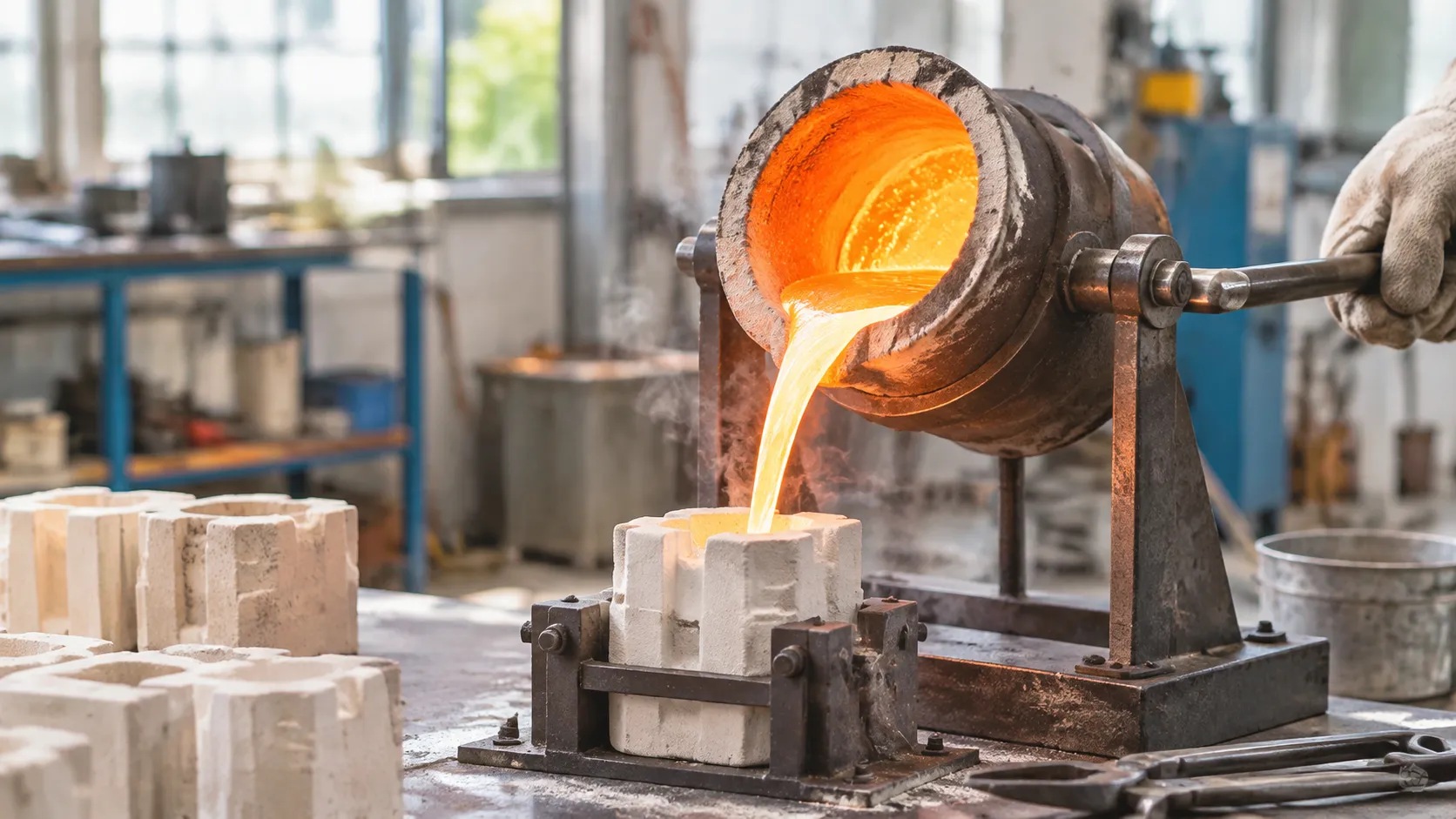
High-temperature sections depend directly on structural integrity at the micro-level. We utilize specialized investment and precision casting services for metal parts to achieve net-shape accuracy with minimal material waste.
- Single-Crystal Casting (SX): Directional solidification eliminates grain boundaries entirely, maximizing resistance to thermal fatigue and creep.
- Directionally Solidified (DS): Aligns grain boundaries longitudinally along stress axes to improve durability under centrifugal stress.
- Equiaxed Conventional Casting: Yields reliable, cost-effective structural components for moderate-load applications.
Multi-Axis CNC Machining and Additive Manufacturing
Cast parts require tight dimensional finishing to meet aerodynamic and balancing specs. We combine multi-axis CNC milling, wire EDM, and metal additive manufacturing:
- 5-Axis Precision Machining: Delivers micron-level tolerances across complex airfoils, dynamic root forms, and labyrinth seal channels.
- Direct Metal Laser Sintering (DMLS): Builds intricate internal cooling galleries and fuel swirler geometries impossible to machine via traditional tooling.
- Automated Polishing: Cleans leading and trailing edges to target surface roughness values, optimizing airflow efficiency.
Aerospace Certifications and Quality Control
Operating a certified supply line means tracking every turbine engine component from raw melt to delivery. Adhering to verified casting quality standards for reliable metal parts protects engines from in-flight failures and unplanned teardowns.
- AS9100 and ISO 9001 Alignment: Complete traceability on all heats, material chemistries, and secondary operations.
- Non-Destructive Testing (NDT): Fluorescent penetrant inspection (FPI) and multi-angle digital X-ray uncover hidden subsurface voids, hot tears, and inclusions.
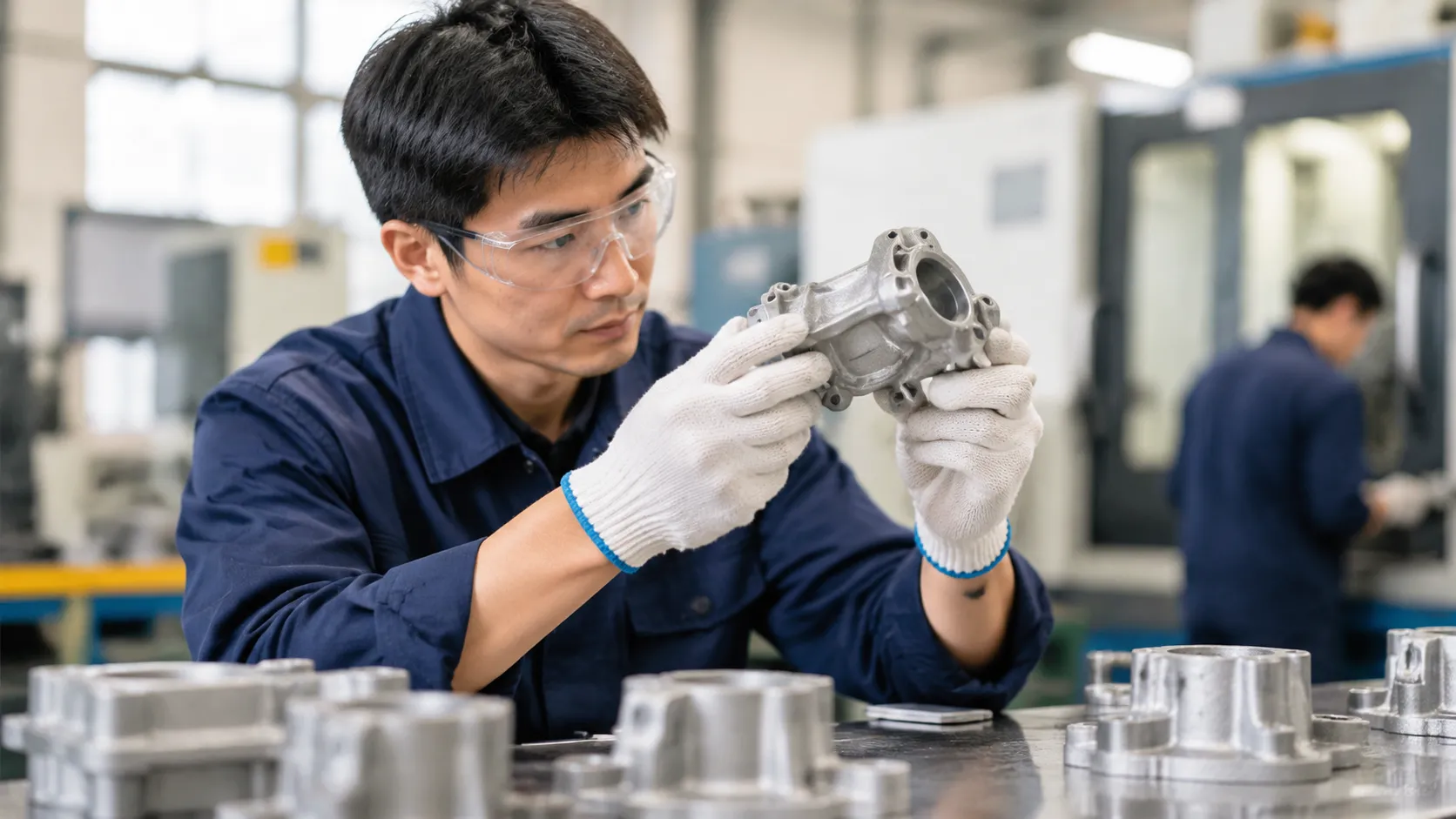
- CMM Verification: High-precision coordinate measuring machines verify airfoil profiles and true position tolerances against original CAD datasets.
Failure Modes and Wear Factors in Turbine Engine Components
Operating in brutal thermal and mechanical environments means every turbine engine component faces predictable wear patterns over time. We monitor these degradation pathways closely to anticipate maintenance windows, prevent catastrophic downtime, and improve hardware longevity.
Creep Deformation and High-Cycle Thermal Fatigue
Continuous centrifugal loading at sustained peak temperatures forces rotating elements to stretch. This permanent elongation—known as creep—eventually compromises tight operational clearances. Alongside creep, rapid power cycling creates extreme thermal gradients between startup, cruise, and shutdown. These fluctuations generate severe cyclic stress, leading to high-cycle thermal fatigue and micro-cracking across high-pressure turbine blade surfaces and disc rims.
High-Temperature Oxidation and Hot Corrosion
Hot-section parts constantly combat chemical breakdown from burning fuel and high-velocity air:
- Type I Hot Corrosion (825°C–950°C): Caused by condensed sodium sulfate salts that dissolve the protective oxide layer on superalloys, accelerating rapid base-metal loss.
- Type II Hot Corrosion (650°C–800°C): Low-temperature pitting triggered by sulfur trioxide and localized salt eutectics, targeting blade roots and nozzle guide vanes.
- Direct Oxidation: Sustained contact with excess oxygen at temperatures over 1000°C strips unshielded base metals, requiring advanced barrier coatings to preserve structural integrity.
Foreign Object Damage (FOD) and Leading-Edge Erosion
Ingested runway debris, birds, hail, and airborne dust cause immediate mechanical trauma or progressive surface degradation. Fan assemblies and titanium compressor blades take the brunt of Foreign Object Damage (FOD), resulting in direct nicks, tears, and bent trailing edges. Meanwhile, continuous exposure to fine atmospheric particulates causes leading-edge erosion, disturbing aerodynamic profiles and dropping stage efficiency.
To withstand these harsh physical environments, our team relies on precision aerospace casting components and solutions designed to meet strict structural integrity standards from day one.
Vibration-Induced Fretting Wear and Dynamic Unbalance
High rotational speeds make assemblies sensitive to minor harmonic shifts. Aerodynamic flutter and mechanical resonance trigger microscopic motion between tightly clamped contact surfaces, such as blade roots and rotor disc dovetails. This friction causes fretting wear, stripping protective coatings and generating localized stress concentrations. If left unchecked, the resulting dynamic unbalance damages bearing journals, compromises seals, and increases overall vibration signatures throughout the entire powertrain.
Turbine Engine Component Repair and Maintenance (MRO)
Keeping critical engine hardware flight-ready requires tight maintenance cycles and proven restoration techniques. We focus on extending the operating life of every high-value turbine engine component through advanced diagnostics, precision material build-up, and certified tracking.
Borescope Inspection and Crack Detection Methods
Routine health monitoring starts inside the engine without complete teardown: Digital Video Borescopes: We use high-articulation optical probes to detect early blade tip curl, thermal coating loss, and foreign material impact. Fluorescent Penetrant Inspection (FPI): High-sensitivity liquid penetrants reveal micro-cracks along turbine blade airfoils and root attachments under UV light. Eddy Current Testing: Pinpoints subsurface stress fractures around disc bolt holes and dynamic seal slots. Automated Non-Destructive Scanning: Integrating precision robotics and vision inspection ensures repeatable defect mapping on complex geometry before teardown begins.
Blade Tip Restoration, Weld Repairs, and Laser Cladding
Worn dimensions do not mean an automatic scrap tag. We restore structural integrity using targeted build-up processes: Laser Powder Cladding: Applies minimal heat input to rebuild squealer tips and leading edges on high-pressure turbine blades, eliminating parent-metal distortion. Micro-Plasma and TIG Welding: Fills localized erosion grooves and trailing-edge nicks on guide vanes and combustor assemblies. Precision Profile Machining: High-speed CNC grinding blends repaired surfaces back to exact aerodynamic tolerances.
Surface Recoating and Environmental Barrier Stripping
Thermal stress quickly degrades protective layers. Our overhaul process strips and resets the protection envelope: Chemical and Mechanical Stripping: Removes degraded thermal barrier coatings (TBC) and oxidized bond coats without eroding the base superalloy substrate. Platinum Aluminide Diffusion: Replenishes oxidation barriers in the mid-temperature zones of nozzle guide vanes. EB-PVD and Air Plasma Spray (APS): Reapplies yttria-stabilized zirconia (YSZ) ceramic topcoats to shield base metals from extreme combustor gas flows.
Lifecycle Tracking: OEM Original Parts vs. FAA-PMA Alternatives
Managing maintenance costs requires a clear strategy between factory equipment and certified replacements:
| Criteria | OEM Original Parts | FAA-PMA Certified Alternatives |
|---|---|---|
| Traceability | Direct manufacturer documentation and historical serial records | Backed by FAA test and computation approvals (8130-3 tagged) |
| Material Match | Baseline engine manual alloy specifications | Equivalent or improved superalloy reverse-engineered specs |
| Procurement Cost | Standard list pricing with strict lead-time dependence | 20% to 40% reduction in direct replacement expenditure |
| Lifecycle Data | Extensive fleet-wide flight hour logs | Rigorous airworthiness tracking matching OEM cycle limits |
Balancing these options gives operators full control over overhaul budgets while keeping fleet safety and airworthiness uncompromised.
Sourcing and Selection Criteria for Turbine Engine Components
Procuring the right turbine engine component requires balancing flight safety, direct operating costs, and supply chain lead times. We evaluate every part against rigorous mechanical, regulatory, and lifecycle standards to ensure dependable on-wing performance.
Material Traceability and Airworthiness Certification
Never accept hardware without complete pedigree documentation. Every mission-critical turbine engine component must arrive with authenticated regulatory paperwork to enter operational inventory: Airworthiness Approval Tags: Dual-release FAA Form 8130-3 or EASA Form 1 verifying airworthiness and conformity. Full Traceability: Certified Material Test Reports (CMTR) matching specific heat-lot numbers, mill sources, and melt batches. Non-Destructive Testing Records: Signed inspection logs verifying fluorescent penetrant, ultrasonic, or eddy current evaluations.
Operating Limits: Thermal Margins, Thrust, and Duty Cycles
Engine hardware must match the exact operating envelope of your airframe or power-generation package: Thermal Margins: Confirm whether high-temperature gas turbine parts maintain adequate cooling margins under full-thrust or base-load operations. Duty Cycle Profile: Match alloy fatigue limits to your flight profiles—short-haul cyclic routes stress components differently than long-range continuous cruising. Manufacturing Integrity: When evaluating structural casings versus rotor disks, we weigh fabrication methods through a practical forging and casting comparison to confirm structural grain flow and fatigue thresholds.
| Selection Metric | Key Verification Factor | Operational Impact |
|---|---|---|
| Material Provenance | FAA 8130-3 / EASA Form 1 / CMTR | Immediate compliance & legal install |
| Fatigue Capability | Low-Cycle Fatigue (LCF) limits | Safe service-interval scheduling |
| Repair Allowance | OEM Engine Manual limits | Multi-run overhaul viability |
| TCO Profile | Mean Time Between Removals (MTBR) | Minimized unscheduled shop visits |
Lead Times, Repairability Limits, and Supplier Support
A low-cost part delivers zero value if unworkable lead times ground your assets. We assess supplier capabilities across three operational gates: Off-the-Shelf Availability: Established stocking pools for high-wear turbine engine component inventory to mitigate AOG (Aircraft On Ground) exposure. Repair Limits: Explicit dimensional wear tolerances per the engine manual, ensuring the hardware can undergo multiple tip-restorations or weld repairs. Technical Backing: Direct engineering support for rapid disposition of non-conformances and warranty claims.
Unit Cost vs. Total Cost of Ownership (TCO)
Acquisition cost represents only a fraction of the component's true operational impact. We weigh upfront pricing directly against expected lifecycle value: Initial Price vs. MTBR: Cheaper, low-life hardware drastically inflates overall engine shop visit frequency. Scrap Rates: High-grade alloys and coatings provide higher turnaround yield at overhaul, lowering per-hour operating costs. PMA vs. OEM Integration: We calculate the amortized savings of alternative certified parts against residual engine market value.
Frequently Asked Questions About Turbine Engine Components
What is the most critical turbine engine component?
The high-pressure turbine (HPT) blade is universally considered the most critical turbine engine component. Operating directly downstream of the combustion chamber, HPT blades withstand centrifugal loads exceeding 10,000 RPM at gas temperatures that surpass the melting point of bare metal. A failure here causes immediate downstream engine damage, making structural integrity in this stage vital.
How often do high-pressure turbine (HPT) blades need replacement?
Service intervals depend entirely on operational duty cycles, flight profiles, and thermal margins. Flight Hours: Commercial operators generally run HPT sets between 15,000 to 25,000 flight hours before life-limited replacement. Flight Cycles: High-cycle regional operations require earlier shop visits due to rapid thermal cycling. Routine Borescope Checks: On-wing inspections track leading-edge erosion, coating loss, and burning between standard overhaul intervals.
What are the differences between OEM and PMA turbine components?
Both component types must meet stringent civil aviation airworthiness requirements, but they differ in design ownership and pricing:
| Feature | OEM Components | FAA-PMA Components |
|---|---|---|
| Design Ownership | Engine manufacturer proprietary IP | Independent engineering with FAA approval |
| Material & Performance | Baseline operational standard | Form, fit, and function equivalent or identical |
| Cost Profile | Standard list price | 20% to 40% lower acquisition cost |
| Documentation | Traceable to type-certificate holder | FAA-PMA designation with Form 8130-3 |
Why are single-crystal alloys used in high-pressure turbine blades?
Traditional casting methods leave microscopic grain boundaries where cracks and thermal creep initiate under centrifugal load. Single-crystal nickel superalloys eliminate grain boundaries entirely through directional solidification techniques. Advanced processes like lost wax casting turbine blades align the crystal lattice along the principal stress axis, delivering superior resistance to creep deformation and thermal fatigue.
How do thermal barrier coatings extend turbine component service life?
Thermal barrier coatings (TBCs) act as ceramic insulation between burning gas paths and structural metals: Temperature Drop: Modern ceramic coatings reduce base substrate metal temperatures by 100°C to 300°C. Oxidation Defense: The ceramic layer seals the underlying superalloy from corrosive combustion gases. Extended Life: By mitigating thermal stress, TBCs prevent premature micro-cracking and significantly stretch hot section shop intervals for every critical turbine engine component.
 English
 Russian
 German